Electrodialyzer and solution treating method thereof

A technology of electrodialyzer and electrode plate, which is applied in the field of solution treatment equipment, and can solve the problem of single solution treatment

Pending Publication Date: 2017-05-24
ZHEJIANG DOWAY ADVANCED TECH CO LTD
View PDF7 Cites 9 Cited by
  • Summary
  • Abstract
  • Description
  • Claims
  • Application Information

AI Technical Summary

Problems solved by technology

[0003] The present invention mainly aims at the problem of singleness of solution treatment in existing electrodialyzers, and invents an electrodialyzer. By improving the structure of separators and ion exchange membranes, multiple (at least four) unique The compartment structure and multiple flow channels form a variety of (at least four) different solutions in and out of the flow channel; then the solutions composed of two or more different ions enter specific flow channels respectively, and are driven by electricity , after flowing out of the corresponding flow channel, the recombination between different ions can be realized, and a solution with two new ion formation forms can be produced

Method used


Image

  • Electrodialyzer and solution treating method thereof
  • Electrodialyzer and solution treating method thereof
  • Electrodialyzer and solution treating method thereof

Examples


Embodiment 1

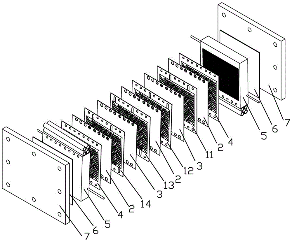
[0053] Such as figure 1 As shown, a plate-and-frame electrodialyzer includes end plates 7, rubber gaskets 6, electrode plates 5, membrane stacks from outside to inside, and is used to connect end plates 7, rubber gaskets 6, electrode plates 5 , The fasteners for fastening connection of membrane stacks.

[0054] The membrane stack partitions, cation exchange membranes 2, and anion exchange membranes 3 are arranged at intervals; wherein, the partitions located at the outermost two ends of the membrane stack are end partitions 4, located between the anion exchange membrane 3 and the cation exchange membrane 2 The clapboard is the middle clapboard.

[0055] The specific arrangement structure of the membrane stack is:

[0056] End partition 4—cation exchange membrane 2—first intermediate partition 11—anion exchange membrane 3—second intermediate partition 12—cation exchange membrane 2—third intermediate partition 13—anion exchange membrane 3— The fourth type of intermediate part...

Embodiment 2

[0093] X is set as the liquid water to be treated, and Y is set as the liquid water to be treated;

[0094] AB is the ion of liquid potassium chloride aqueous solution to be treated, and wherein, A is potassium ion, and B is chloride ion;

[0095] CD is the ion of the liquid humic acid aqueous solution to be treated, wherein, C is a hydrogen ion, and D is a humate ion.

[0096] The specific steps of solution processing are:

[0097] Through 4 different water inlet pipes, X flows into the second type ion migration compartment 23, Y flows into the second type ion migration compartment 21, potassium chloride aqueous solution (AB) flows into the first type ion migration compartment 22 , the aqueous solution of humic acid (CD) flows into the second type ion migration compartment 24 .

[0098] Potassium chloride is used as the polar water in the electrode chamber on the positive side, and potassium chloride is used as the polar water in the electrode chamber on the negative electr...

Embodiment 3

[0104] X is set as the liquid sodium chloride water to be processed, and Y is set as the liquid sodium chloride water to be processed;

[0105] AB is the ion of liquid potassium sulfate aqueous solution to be treated, and wherein, A is potassium ion, and B is sulfate ion;

[0106] CD is the ions of the mixed aqueous solution of magnesium nitrate and calcium chloride to be treated, wherein C is magnesium ions and calcium ions, and D is nitrate ions and chloride ions.

[0107] The specific steps of solution processing are:

[0108] Through 4 different water inlet pipes, X flows into the second type ion migration compartment 23, Y flows into the second type ion migration compartment 21, potassium sulfate aqueous solution (AB) flows into the first type ion migration compartment 22, The mixed aqueous solution of magnesium nitrate and calcium chloride (CD) flows into the second type of ion migration compartment 24 .

[0109] Potassium sulfate is used as the polar water in the posi...


PUM


Abstract

The invention relates to an electrodialyzer and a solution treating method thereof. The structures of a partition board and an ion exchange membrane are improved, so that multiple unique compartment structures and multiple flow channels are formed between membrane stacks, thereby forming multiple different solution inlet and outlet flow channels; and two or more solutions formed by different ions respectively enter specific flow channels, and the recombination of different ions can be realized after the solution flows out of the corresponding flow channels under an electric driving effect, thereby producing two new solutions in ion constitution forms. The liquid treating method comprises the following specific steps: X flows into a second kind of ion immigration compartment, Y flows into a first kind of ion immigration compartment, A and B flow into a first kind of ion migration compartment, and the C and D flow into a second kind of ion migration compartment; under the driving of an electric field, A and C move to a cathode direction, and B and D move to an anode direction; and positive ions and negative ions are recombined in different compartments so as to form new solutions flowing out of four different water outlet pipelines.

Description

technical field [0001] The invention relates to solution treatment equipment, in particular to an electrodialyzer and a solution treatment method thereof, which are used for ion recombination, chemical production, water treatment and the like. Background technique [0002] Electrodialysis is a method that utilizes the permselectivity of ion exchange membranes to separate different solute particles such as ions. Driven by the electric field, the charged solute particles (such as ions) in the solution migrate in a specific direction through the ion exchange membrane, thereby realizing the separation and concentration of ions. Originally used for seawater desalination, it is now widely used in chemical industry, light industry, metallurgy, papermaking and pharmaceutical industries. The electrodialyzers currently on the market generally only have two solution flow channels, the concentrated chamber and the dilute chamber, so that they can only concentrate or separate the same s...

Claims


Application Information

Patent Timeline
Patent Type & Authority Applications(China)
IPC IPC(8): B01D61/46
CPCB01D61/46B01D2311/2684
Inventor 施小东施秦峰刘泽宇
Owner ZHEJIANG DOWAY ADVANCED TECH CO LTD
Why Eureka
Try Eureka