
A punching and forming equipment for the side of a compressor shell

A technology for compressor shells and forming equipment, applied in forming tools, metal processing equipment, piercing tools, etc., can solve the problems of large occupied area, low degree of automation, and low production efficiency, and achieve small occupied area and high degree of automation High, the effect of improving production efficiency

Active Publication Date: 2018-08-10
FOSHAN SHUNDE KAISHUO PRECISION MOLD AUTOMATION TECH CO LTD +1
View PDF6 Cites 0 Cited by
  • Summary
  • Abstract
  • Description
  • Claims
  • Application Information

AI Technical Summary

Problems solved by technology

When the existing compressor casing is processed, it is necessary to punch multiple holes in different positions, so multiple punching processes are required, but the existing compressor casing punching equipment is composed of multiple punching equipment and multiple feeding manipulators Therefore, the existing compressor shell punching equipment has low production efficiency, is not suitable for mass processing, occupies a large area, high production cost, low degree of automation, and unsatisfactory processing quality

Method used


Image

  • A punching and forming equipment for the side of a compressor shell
  • A punching and forming equipment for the side of a compressor shell
  • A punching and forming equipment for the side of a compressor shell

Examples


Embodiment Construction

[0055] The present invention will be further described below in conjunction with the accompanying drawings and embodiments.

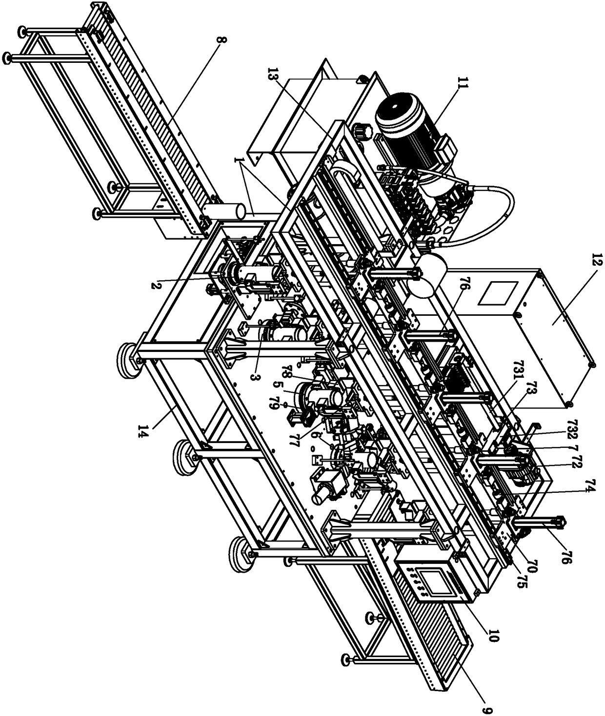
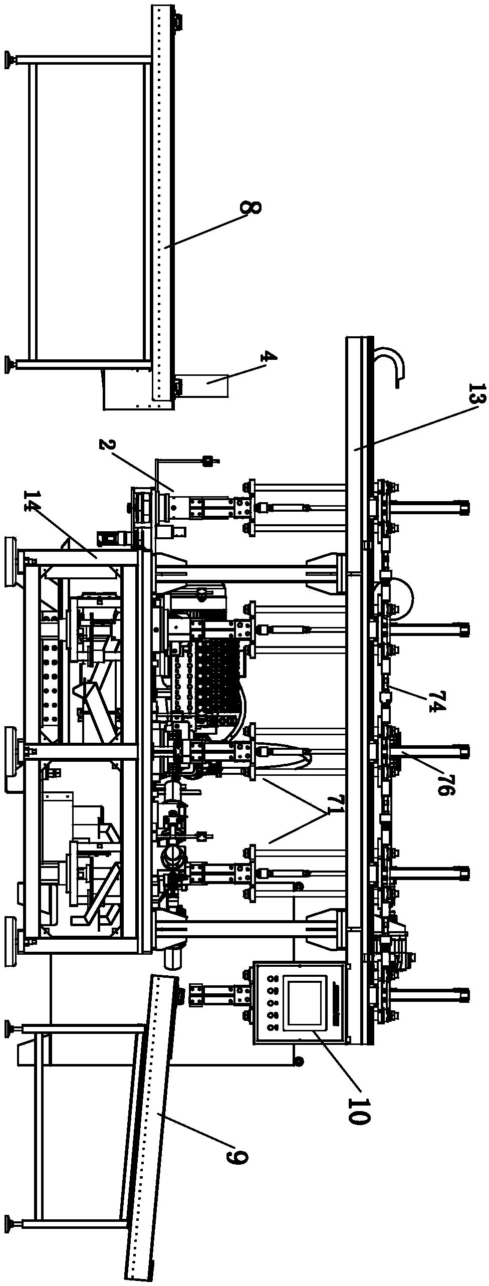
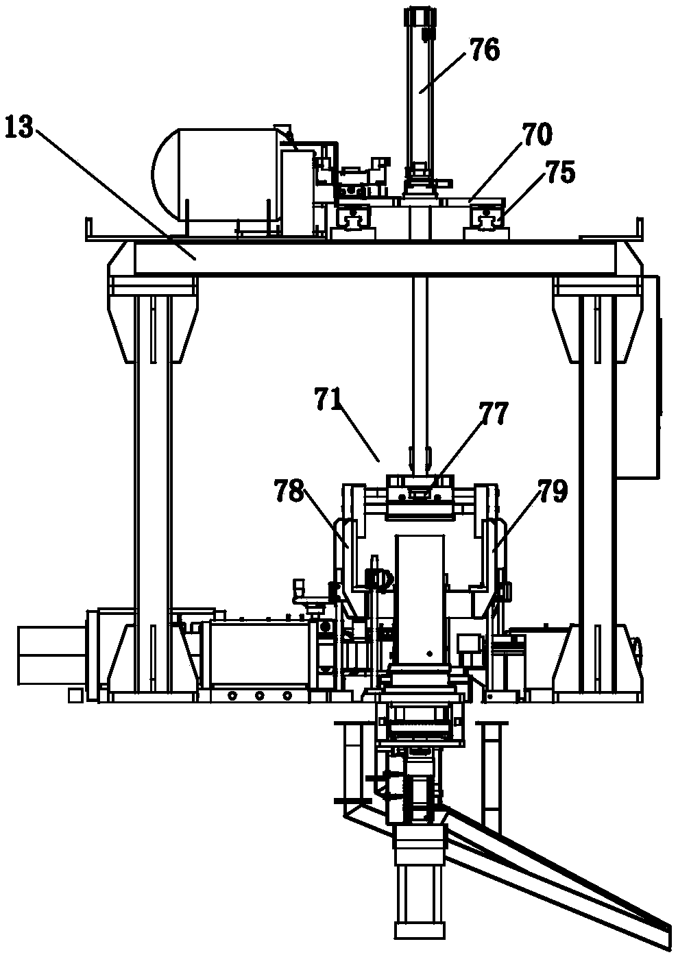
[0056] See Figure 1 to Figure 24 As shown, a compressor shell side punching forming equipment includes a frame 1, a control device 10, an oil pressure system 11, an electric cabinet 12, a shell feeding and positioning conveyor 8, a weld detection and positioning mechanism 2, a horizontal Feeding mechanism 7 , preformed convex hull and side punching small hole mechanism 3 , convex hull forming and side punching large hole mechanism 5 , three-hole side punching mechanism 6 and shell discharge conveyor 9 . The frame 1 includes an upper frame 13 and a lower base 14 , and the upper frame 13 is arranged on the upper part of the lower base 14 .

[0057] The control device 10 is used to control the work of the whole equipment;

[0058] The hydraulic system 11 provides hydraulic oil for the whole equipment.

[0059] The electric cabinet 12 supplies power for...


PUM


Abstract

The invention relates to compressor shell side face punching forming equipment which comprises a rack, a weld inspection positioning mechanism, a convex hull preforming and small hole side punching mechanism, a convex hull forming and large hole side punching mechanism, and a three-hole side punching mechanism, wherein the weld inspection positioning mechanism is used for detecting the position of a welding line in a compressor shell and rotating and positioning the compressor shell; the convex hull preforming and small hole side punching mechanism is used for preforming a prototype convex hull on the outer side wall of the compressor shell and punching a small hole in the prototype convex hull; the convex hull forming and large hole side punching mechanism is used for integrating the prototype convex hull into a formed convex hull and punching the small hole into a larger hole; and the three-hole side punching mechanism is used for punching three holes in the outer side wall of the compressor shell in the circumferential direction. According to the invention, the three punching mechanisms for different holes sites are arranged on the rack and are integrated on the rack, so that the occupied area is small; in addition, a horizontal feeding mechanism on the rack can realize synchronous feeding and discharging; and the compressor shell side face punching forming equipment can quickly finish punching procedures of different hole sites, is high in working efficiency and degree of automation, and improves the production efficiency.

Description

technical field [0001] The invention relates to a compressor casing punching device, in particular to a compressor casing side punching forming device. Background technique [0002] The compressor is a driven fluid machine that upgrades low-pressure gas to high-pressure gas. It is the heart of the refrigeration system and provides power for refrigeration. Among them, the compressor shell plays a vital role in the normal operation of the compressor. role. When the existing compressor casing is processed, it is necessary to punch multiple holes in different positions, so multiple punching processes are required, but the existing compressor casing punching equipment is composed of multiple punching equipment and multiple feeding manipulators Therefore, the existing punching equipment for compressor shells has low production efficiency, is not suitable for mass processing, occupies a large area, has high production costs, low degree of automation, and unsatisfactory processing ...

Claims


Application Information

Patent Timeline
Patent Type & Authority Patents(China)
IPC IPC(8): B21D35/00B21D22/04B21D28/28B21D37/10B21D28/34B21D43/10B21C51/00
CPCB21C51/00B21D22/04B21D28/28B21D28/285B21D28/34B21D35/001B21D37/10B21D43/105
Inventor 谢传海钟吉民
Owner FOSHAN SHUNDE KAISHUO PRECISION MOLD AUTOMATION TECH CO LTD
Learn More