
Microwave signal photonic frequency conversion and multichannel fiber transmission device and method

A technology of optical fiber transmission and microwave signal, which is applied in the field of optical communication and microwave, and can solve the problems of difficult implementation, poor frequency adjustability, power fading, etc.

Active Publication Date: 2017-05-10
XIDIAN UNIV +1
View PDF3 Cites 25 Cited by
  • Summary
  • Abstract
  • Description
  • Claims
  • Application Information

AI Technical Summary

Problems solved by technology

[0004] However, in commonly used photonics frequency conversion systems, the electro-optic modulation of radio frequency (RF) and local oscillator (LO) signals is double-sideband modulation. After the optical mixing signals modulated by RF and LO are transmitted through optical fibers, the mixing The up-converted or down-converted signal after frequency conversion may experience severe power fading, which has a great impact on communication quality
Moreover, the power fading is affected by the frequency of the signal before and after frequency conversion, the length of the optical fiber, and the wavelength of the optical carrier
[0005] Single-side charged optical modulation technology can be used to solve the problem of power fading. However, the current single-side charged optical modulation technology generally requires the use of electric phase shifters or optical filters, which is difficult to implement and poor in frequency adjustability.

Method used


Image

  • Microwave signal photonic frequency conversion and multichannel fiber transmission device and method
  • Microwave signal photonic frequency conversion and multichannel fiber transmission device and method
  • Microwave signal photonic frequency conversion and multichannel fiber transmission device and method

Examples


Embodiment Construction

[0024] The embodiments of the present invention are described in detail below in conjunction with the accompanying drawings: this embodiment is implemented on the premise of the technical solution of the present invention, and detailed implementation methods and specific operating procedures are provided, but the protection scope of the present invention is not limited to the following The described embodiment:

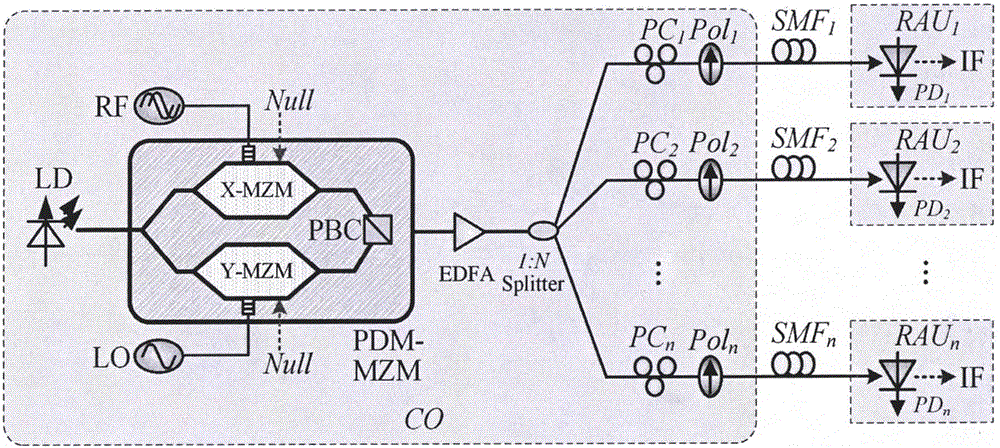
[0025] Such as figure 1 As shown, in this embodiment, the device includes: LD, RF signal source, LO signal source, PDM-MZM (including Y-type splitter, X-MZM, Y-MZM, PBC), EDFA, 1:4 optical splitter Router, PC, Pol, SMF, PD. LD is connected to PDM-MZM and EDFA in turn, and EDFA is followed by a 1:4 optical splitter. The output end of the 1:4 optical splitter is connected to 4 optical fiber links with the same structure, and the i-th (i=1, 2, 3, 4) link is connected to PCi, Poli and SMFi in sequence. The output terminal of SMFi is connected to PDi, and the frequency ...


PUM


Abstract

The invention discloses a microwave signal photonic frequency conversion and multichannel fiber transmission device and method realized by a polarization multiplexing modulator. The device, as shown by a figure, comprises a laser diode (LD), a polarization multiplexing Mach-Zehnder modulator (PDM-MZM), an erbium doped fiber amplifier (EDFA), a 1:N light splitter (Splitter), a polarizer (Pol), a polarization controller (PC), and a standard single-mode fiber (SMF) and a photoelectric detector (PD). The PDM-MZM is used to carry out carrier suppressed double side band modulation on radio frequency (RF) and local oscillation (LO) signals and then implement frequency mixing, and the RF and LO isolation degree of frequency conversion gain and frequency conversion signals is improved. Optical signals output by the modulator can be divided into multiple paths to implement fiber transmission, each path is adjusted via an independent polarization state, and power attenuation caused by dispersion can be compensated.

Description

technical field [0001] The invention relates to the technical field of optical communication and microwave technology, in particular to photonic frequency conversion of microwave signals and multi-channel optical fiber transmission in the optical communication technology. Background technique [0002] In the Internet era, the amount of information is increasing rapidly, and the demand for media data streams is also increasing. Coupled with the popularity of smart phones, people have higher and higher requirements for network bandwidth and mobility. In this context, the Radio-over-Fiber (RoF) communication system has great development prospects, because it not only has the advantages of large bandwidth, high speed, and anti-electromagnetic interference of optical fiber communication, but also has the advantages of wireless communication interface. With the characteristics of flexible access and strong mobility, RoF communication is the development direction of broadband wirel...

Claims


Application Information

Patent Timeline
IPC IPC(8): H04B10/2575H04B10/2507H04B10/2587H04B10/50H04B10/516H04B10/564
CPCH04B10/2507H04B10/25758H04B10/2587H04B10/503H04B10/5165H04B10/564
Inventor 高永胜文爱军徐新瑶谭庆贵梁栋
Owner XIDIAN UNIV
Learn More