
Equipment for soaking cells

A battery cell and equipment technology, which is applied in the field of soaking battery cell equipment, can solve problems such as low production efficiency, uneven electrolyte distribution, damage, etc., and achieve the effect of improving the soaking efficiency

Active Publication Date: 2019-06-25
BAOSHAN IRON & STEEL CO LTD
View PDF7 Cites 0 Cited by
  • Summary
  • Abstract
  • Description
  • Claims
  • Application Information

AI Technical Summary

Problems solved by technology

[0005] CN103872381A relates to a method for statically injecting power batteries, in which two methods are compared: 1. After the electrolyte is injected, it is left to stand for 12-24 hours in a workshop with dry air. The siphon effect is not ideal, resulting in slow electrolyte infiltration, low production efficiency, high internal resistance and poor cycle life; Vacuum and pressurize three times. After each vacuuming or pressurization, stand for a certain period of time, and then release the pressure of the power battery to normal pressure to enter the subsequent process.
In this process, there are two problems in one-time vacuuming and pre-sealing after the liquid injection is completed: 1. The unabsorbed electrolyte is unevenly distributed due to one-time vacuuming; 2. The contact process between the electrolyte and the electrode after the cell injection A chemical reaction will occur in the gas to generate gas, thereby releasing the force of a vacuum to compress the cell or destroying the vacuum degree. The failure of the vacuum will affect the siphon effect of the electrode and the diaphragm, and reduce the electrolyte infiltration efficiency.

Method used


Image

  • Equipment for soaking cells

Examples


Embodiment 1

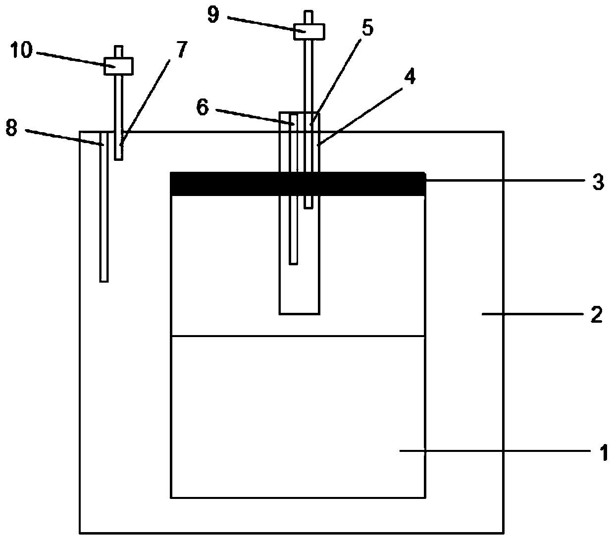
[0057] Step 1. Put the battery cell 1 that has been injected into the cavity 2, put the air bag of the battery cell 1 on the sleeve 4 and fix it with the seal 3;

[0058] Step 2: Pressurize the cavity 2 to 100KPa through the dry compressed nitrogen gas inlet 8, vacuumize the inside of the cell to -60KPa through the conduit 5, close the valve 9, and let it stand for 10 minutes;

[0059] Step 3: Open the valve 10 to restore the normal pressure in the cavity 2, inject dry nitrogen into the cell 1 airbag through 6 to pressurize to 100KPa, and let it stand for 10 minutes;

[0060] Step 4: pressurize the cavity 2 to 100KPa through the dry compressed nitrogen gas inlet 8, vacuumize the interior of the cell to 100KPa through the conduit 5, close the valve 9, and let it stand for 10 minutes;

[0061] Step 5. Open the valve 10 to restore the normal pressure in the cavity 2, inject dry nitrogen into the cell 1 airbag through 6 to pressurize to 100KPa, and let it stand for 10 minutes;

...

Embodiment 2

[0065] Step 1. Put the battery cell 1 that has been injected into the cavity 2, put the air bag of the battery cell 1 on the sleeve 4 and fix it with the sealing clip 3;

[0066] Step 2: Pressurize the cavity 2 to 300KPa through the dry compressed nitrogen gas inlet 8, vacuumize the interior of the cell to -60KPa through the conduit 5, close the valve 9, and let it stand for 30 minutes;

[0067] Step 3: Open the valve 10 to restore normal pressure in the cavity 2, inject dry nitrogen into the cell 1 airbag through 6 to pressurize to 300KPa, and let it stand for 30 minutes;

[0068] Step 4: Pressurize the cavity 2 to 100KPa through the dry compressed nitrogen gas inlet 8, vacuumize the interior of the cell to -100KPa through the conduit 5, close the valve 9, and let it stand for 30 minutes;

[0069] Step 5. Open the valve 10 to restore the normal pressure in the chamber 2, inject dry nitrogen into the cell 1 airbag through 6 to pressurize to 300KPa, and let it stand for 30 minu...


PUM


Abstract

Embodiments of the present invention provide a device and method for infiltrating a battery cell, the battery cell is a soft-packed lithium battery cell, and the device includes: a first connecting member, one end of which is connected to the first air pressure regulating device; The other end of the connecting piece is fixed and communicated with the cavity, the cavity can accommodate the electric core, and the first air pressure regulating device pressurizes and depressurizes the cavity; the second connecting piece, one end of which is connected to the second air pressure regulating device, the electric cell The air bag of the core is fixed and communicated with the other end of the second connecting member, the second air pressure regulating device pressurizes and depressurizes the battery cell through the second connecting member, and the sealing member seals the opening part of the air bag of the battery cell to The cavity isolates the inside of the cell from the outside. In the embodiment of the present invention, since the inside of the cell is isolated from the outside in the cavity, an ideal pressure difference can be formed, which enhances the capillary-like phenomenon inside the cell and accelerates the bursting of bubbles, thereby improving the electrolyte infiltration efficiency .

Description

technical field [0001] The invention relates to the technical field of lithium batteries, and more specifically, to a device for soaking electric cores. Background technique [0002] Lithium-ion secondary batteries have the characteristics of high energy density, small size, good discharge point platform characteristics, long cycle life, no memory effect, green and pollution-free, etc., and have broad applications in the fields of electronic products, power tools, new energy vehicles and energy storage power stations. application prospects. [0003] The production process of lithium-ion batteries includes pulping, coating, calendering, slitting, cutting, lamination, tab welding, heat sealing, liquid injection, electrolyte impregnation, chemical composition, etc., in which the electrolyte is soaked in the lithium battery Among the many production processes, it takes the longest time, because sufficient standing can ensure that the electrolyte undergoes a thorough micro-react...

Claims


Application Information

Patent Timeline
Patent Type & Authority Patents(China)
IPC IPC(8): H01M10/058H01M10/04
CPCH01M10/0404H01M10/058Y02E60/10Y02P70/50
Inventor 柴明杜国栋吕忱蒋浩民张丕军
Owner BAOSHAN IRON & STEEL CO LTD
Learn More