
Hydraulic parking push rod assembly, automatic transmission and automobile

A parking and push rod technology, applied in the direction of transmission control, components with teeth, belts/chains/gears, etc., can solve the problem of scattered arrangement of piston lock pin electromagnet 6 and parking piston 3, inconvenient assembly, Problems such as large radial size of hydraulic cylinder

Active Publication Date: 2017-05-10
HYCET TRANSMISSION TECH HEBEI CO LTD
View PDF9 Cites 13 Cited by
  • Summary
  • Abstract
  • Description
  • Claims
  • Application Information

AI Technical Summary

Problems solved by technology

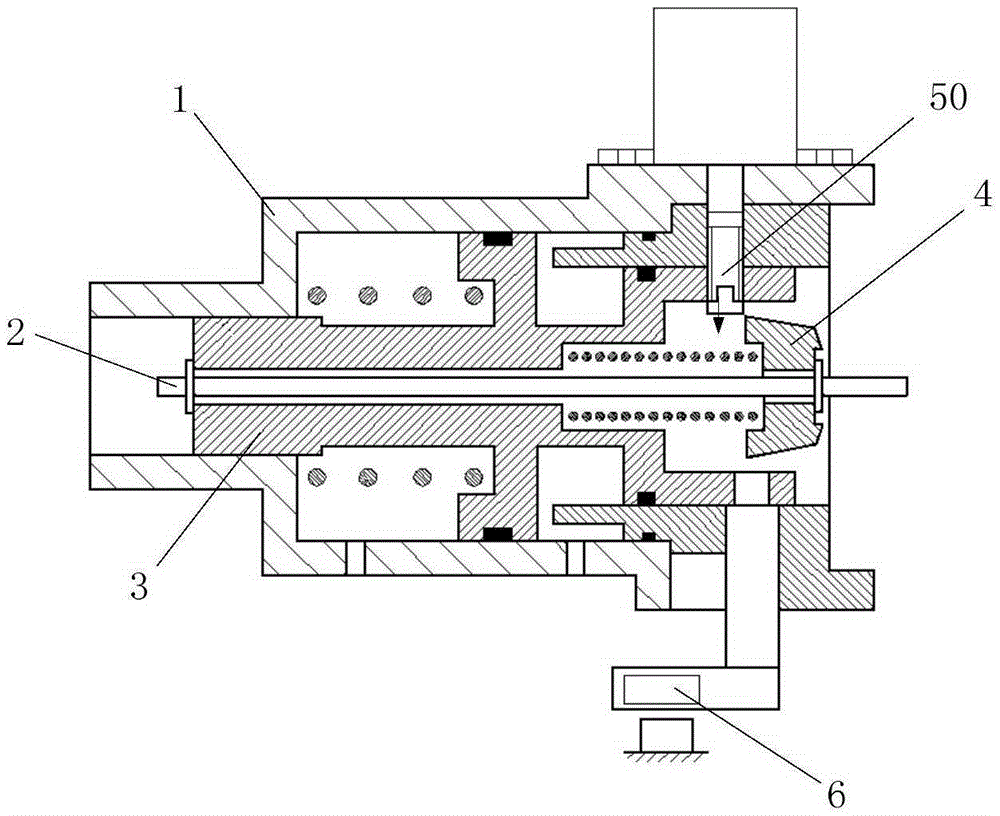
[0005] Although the above-mentioned hydraulic parking mechanism can well realize the parking function of the automobile, because in the hydraulic parking push rod assembly of this hydraulic parking mechanism, the piston lock pin 50, the electromagnet 6 and the parking piston 3 cannot Installed in the same axial direction, the layout of the piston locking pin 50, the electromagnet 6 and the parking piston 3 is scattered, resulting in an excessively large radial dimension of the hydraulic cylinder, which is inconvenient for assembly

Method used


Image

  • Hydraulic parking push rod assembly, automatic transmission and automobile
  • Hydraulic parking push rod assembly, automatic transmission and automobile
  • Hydraulic parking push rod assembly, automatic transmission and automobile

Examples


Embodiment Construction

[0058] It should be noted that, in the case of no conflict, the embodiments of the present invention and the features in the embodiments can be combined with each other.

[0059] The present invention will be described in detail below with reference to the accompanying drawings and examples.

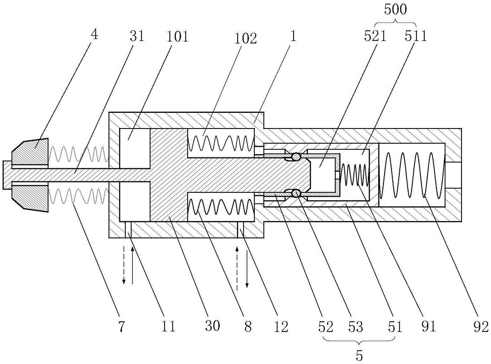
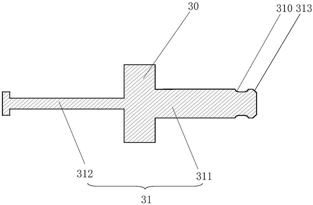
[0060] see figure 2 and Figure 4 ,as well as Figure 10 and Figure 11 , the hydraulic parking push rod assembly provided by the embodiment of the present invention includes: a hydraulic cylinder 1 with a first oil hole 11 and a second oil hole 12, along the direction from the top of the hydraulic cylinder 1 to the bottom of the hydraulic cylinder, The hydraulic cylinder 1 is provided with a piston body 30 and a hydraulic joint 5 sealed with the inner wall of the hydraulic cylinder 1 in sequence. The piston body 30 is arranged on a piston rod 31 capable of engaging and separating from the hydraulic joint 5; the hydraulic joint 5 has a joint Cavity 500; the part between the cylinder...


PUM


Abstract

The invention provides a hydraulic parking push rod assembly, an automatic transmission and an automobile and aims to enable the hydraulic parking push rod assembly to be convenient to mount. The hydraulic parking push rod assembly comprises a hydraulic cylinder with a first oil hole and a second oil hole; a piston body and a hydraulic joint are arranged in the hydraulic cylinder, so that the hydraulic cylinder is divided into a first sealing chamber and a second sealing chamber which are correspondingly communicated with the first oil hole and the second hole; the second sealing chamber is communicated with a joint chamber of the hydraulic joint; one end of a piston rod of the piston body stretches out of the cylinder top or the cylinder bottom; a parking cam is arranged at one end of the piston rod of the piston body; the hydraulic joint is clamped with the piston rod or separated from the piston rod according to a size relationship between the oil pressure of the first sealing chamber and the total oil pressure of the second sealing chamber and the joint chamber, so that non-parking and parking are achieved. According to the hydraulic parking push rod assembly, the piston body and a hydraulic structure in the hydraulic cylinder are linearly distributed along a direction from the cylinder top to the cylinder bottom, so that the radial size of the hydraulic parking push rod assembly is reduced, thus ensuring that the hydraulic parking push rod assembly is convenient to mount. The hydraulic parking push rod assembly is used in the field of automobiles.

Description

technical field [0001] The invention relates to the technical field of automobiles, in particular to a hydraulic parking push rod assembly, an automatic transmission and an automobile. Background technique [0002] An automatic transmission is a car transmission that can automatically change the gear ratio while the vehicle is running. In order to ensure the safety of the car during coasting, a parking mechanism is generally installed in the automatic transmission to ensure that the car can be parked at a certain position or even on a steep slope without time limit. [0003] At present, the common parking mechanism is a hydraulic parking mechanism, including a hydraulic parking push rod assembly, a parking arm and a parking gear sleeved on the input shaft; the structure of the hydraulic parking push rod assembly is as follows: figure 1 As shown, it mainly includes a hydraulic cylinder 1 and a parking piston 3 located in the hydraulic cylinder 1. The parking piston 3 is fixe...

Claims


Application Information

Patent Timeline
Patent Type & Authority Applications(China)
IPC IPC(8): F16H63/34
CPCF16H63/3483
Inventor 赵鹏飞赵双刘照远马得朝聂艳军张浩源
Owner HYCET TRANSMISSION TECH HEBEI CO LTD
Learn More