A garbage compression device and a rear-loading compression garbage truck

A technology of garbage compression and back door, which is applied in the directions of garbage receptacle, transportation and packaging, etc. It can solve the problems of the compression stroke limitation of the compression mechanism, occupying the space of the collecting box, and the compression stroke of the compression mechanism is small, etc., so as to improve the rationality of the bearing force. , Increase the amount of garbage collected, and improve the effect of driving stability

Active Publication Date: 2022-07-22
XIAMEN YULONG MACHINERY
View PDF12 Cites 0 Cited by
  • Summary
  • Abstract
  • Description
  • Claims
  • Application Information

AI Technical Summary

Problems solved by technology

However, in the current garbage collection box with a compression mechanism, the oil cylinder in the compression mechanism needs to be placed in the box, and the oil cylinder will take up a large part of the space in the collection box, reducing the effective garbage carrying space in the collection box, and the compression mechanism. The compression stroke will be limited, so the compression efficiency of garbage is low, and the garbage carrying capacity of the collection box is small, which increases the cost of garbage transfer
[0003] The traditional rear-loading compression garbage truck is also a garbage collection device with a garbage collection box with a compression mechanism, but the compression mechanism of this rear-loading compression garbage truck is at the rear of the garbage box, and the compression stroke of the compression mechanism is small , the garbage compression efficiency is low, and the weight of the compression mechanism will also affect the stability of the garbage truck

Method used


Image

  • A garbage compression device and a rear-loading compression garbage truck
  • A garbage compression device and a rear-loading compression garbage truck
  • A garbage compression device and a rear-loading compression garbage truck

Examples


Embodiment Construction

[0026] The present invention will be further described in detail below with reference to the accompanying drawings and specific embodiments.

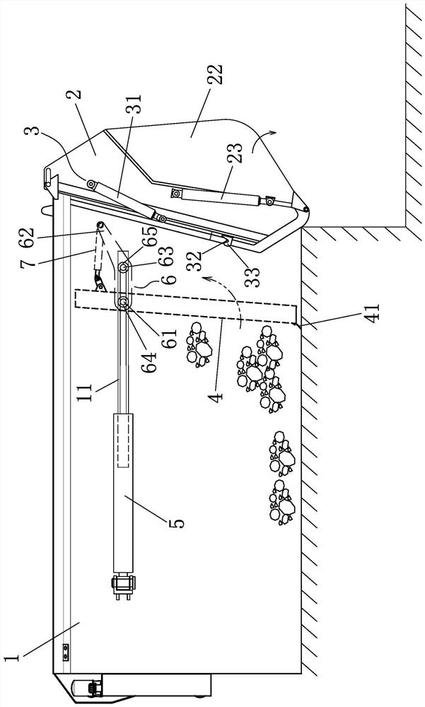
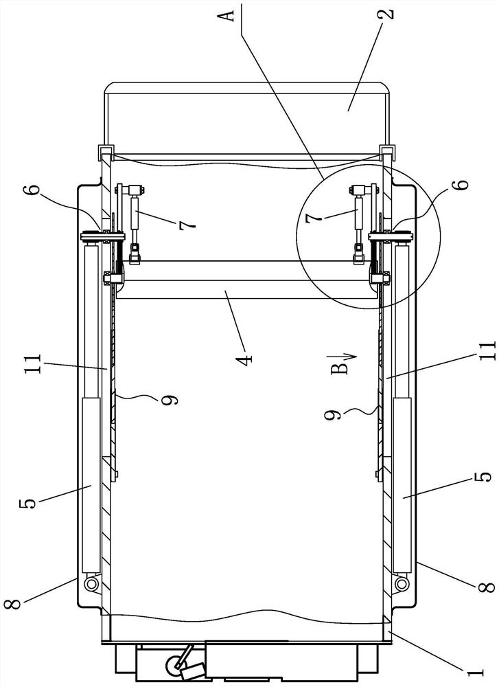
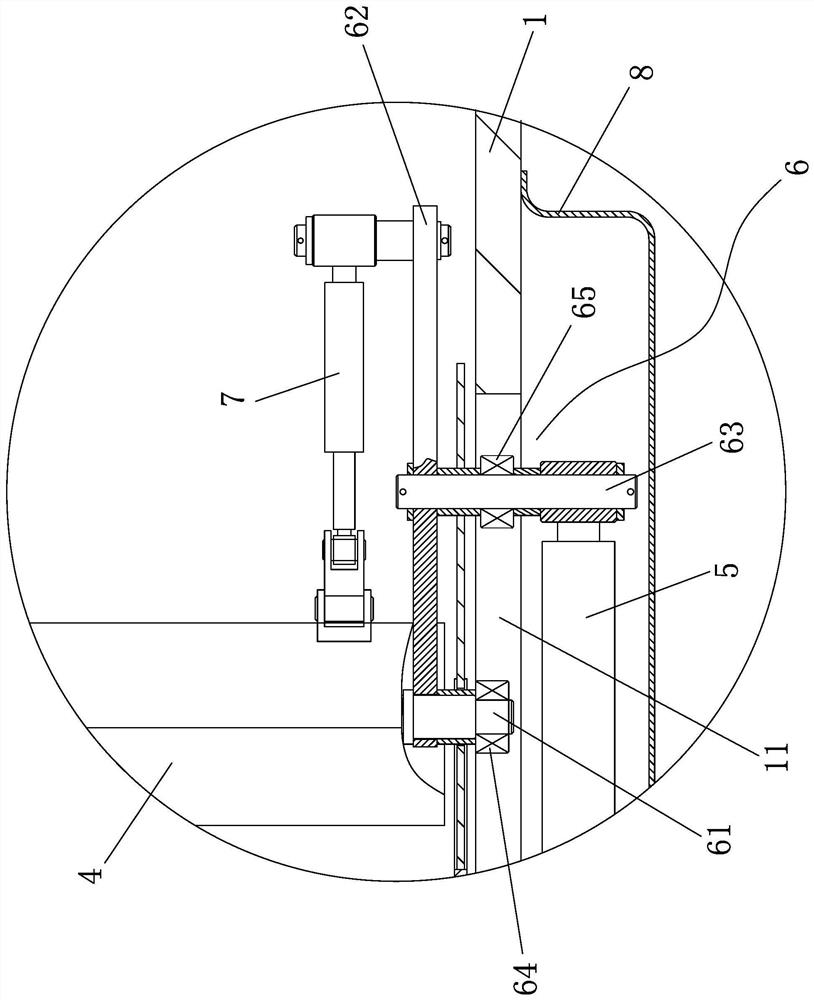
[0027] Figure 1 to Figure 5 As shown, a garbage compressing device includes a box body 1, a rear door 2 is hinged to the rear of the box body 1, a rear door opening or closing mechanism 3 is installed between the rear door 2 and the box body 1, and the rear door 2 is provided with a garbage feeding Port 21, a push plate 4 is installed in the box body 1, and two driving parts are symmetrically installed on the two outer sides of the box body 1. The components of the driving force; two long horizontal through holes 11 are opened on the two sides of the box 1 corresponding to the two push-pull cylinders 5; The push-pull cylinder 5 is connected to the outside, and the push-pull cylinder 5 drives the moving assembly 6 to move along the long horizontal through hole 11 . A rotating oil cylinder 7 is also installed between the sides. One end...


PUM


Abstract

The invention discloses a garbage compression device, comprising a box body, a rear door hinged at the rear of the box body, a garbage feeding port is arranged on the rear door, a push plate is arranged in the box body, and two outer sides of the box body are symmetrically arranged with two For the driving part, the two sides of the box are provided with long horizontal through holes corresponding to the driving parts; each long horizontal through hole is equipped with a moving component, the outer side of the moving component is connected with the driving component, and the driving component drives the moving component along the length of the driving component. The strip-shaped transverse through hole moves, the inner side of the moving assembly and the side of the push plate are hinged through a first pin shaft, and a rotating oil cylinder is also installed between the inner side of the moving assembly and the rear side of the push plate, one end of the rotating oil cylinder is hinged on the inside of the moving assembly, and the other end is hinged On the rear side of the push plate, when the rotating oil cylinder acts, the push plate can be driven to rotate along the first pin shaft. The garbage compression device can increase the garbage bearing space and improve the garbage collection volume of the box body. The present invention also provides a rear-loading compression type garbage truck, comprising a vehicle chassis, and the above-mentioned garbage compression device is installed on the vehicle chassis.

Description

technical field [0001] The invention relates to the technical field of garbage compression equipment manufacturing, in particular to a garbage compression device and a rear-loading compression garbage truck. Background technique [0002] Due to the odor and leakage of garbage from garbage transfer stations or clean buildings, it will cause secondary pollution to the environment. Therefore, the direct transportation system of municipal waste has formed a trend. This requires the garbage collection box to be equipped with a compression mechanism, so that the garbage can be directly pulled to the disposal site after compressing the garbage at the garbage collection site. However, in the current garbage collection box with a compression mechanism, the oil cylinder in the compression mechanism needs to be placed in the box, and the oil cylinder will occupy a large part of the space of the collection box, reducing the effective garbage carrying space in the collection box. The c...

Claims


Application Information

Patent Timeline
Patent Type & Authority Patents(China)
IPC IPC(8): B65F3/14B65F3/26
CPCB65F3/14B65F3/26
Inventor 李振营陈卿雁廖德峰
Owner XIAMEN YULONG MACHINERY
Why Eureka
Try Eureka