Manufacturing method of antenna absorption load

A technology for absorbing loads and manufacturing methods, applied in household components, applications, household appliances, etc., can solve the problems of long processing time, long processing time, human health and environmental impact, etc., achieve high-quality and efficient processing, reduce processing costs, The effect of improving production efficiency

Inactive Publication Date: 2017-05-10
SHANGHAI RADIO EQUIP RES INST
View PDF3 Cites 0 Cited by
  • Summary
  • Abstract
  • Description
  • Claims
  • Application Information

AI Technical Summary

Problems solved by technology

[0002] With the rapid development of electronic technology, new requirements are put forward for magnetic materials. Magnetic components require complex shapes, miniaturization, high dimensional accuracy, high yield, low cost, and integration with other components. However, traditional powder metallurgy and Processing technology, the shape is limited, and the processing time is long and expensive
Among them, the absorbing load is used as a wave-absorbing element, which is widely used in antenna products of various models. The structural characteristics of this type of parts are sharp corners, cones, long strips, etc. The conventional molding process is to manually stir and cast the blank block. Milling cuts into strips and then grinds. This process takes a long time, consumes a lot of money, and has a low pass rate. Among them, the material utilization rate is only about 10%, and the processing scrap rate is 10%-20%. In addition, the dust generated during the process (Particle size below 10μm) has an impact on human health and the environment

Method used


Image

  • Manufacturing method of antenna absorption load
  • Manufacturing method of antenna absorption load
  • Manufacturing method of antenna absorption load

Examples


Embodiment Construction

[0027] The present invention will be further elaborated below by describing a preferred specific embodiment in detail in conjunction with the accompanying drawings.

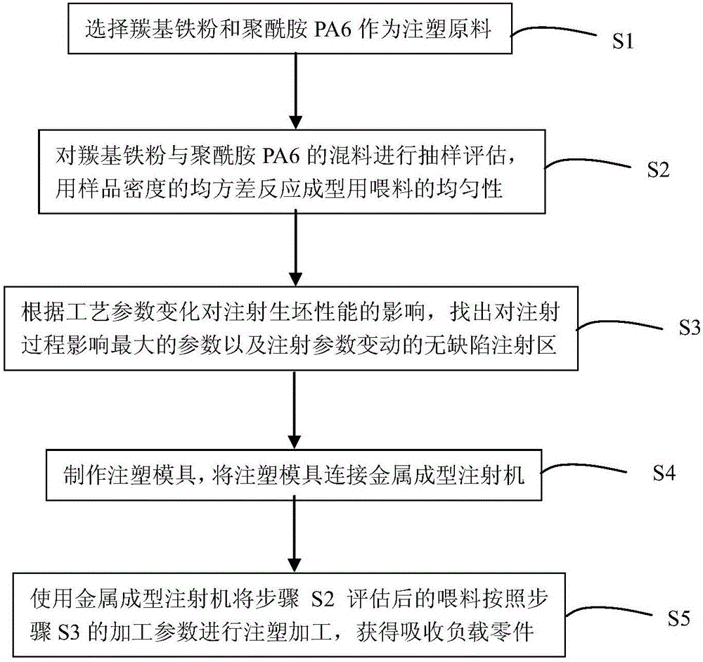
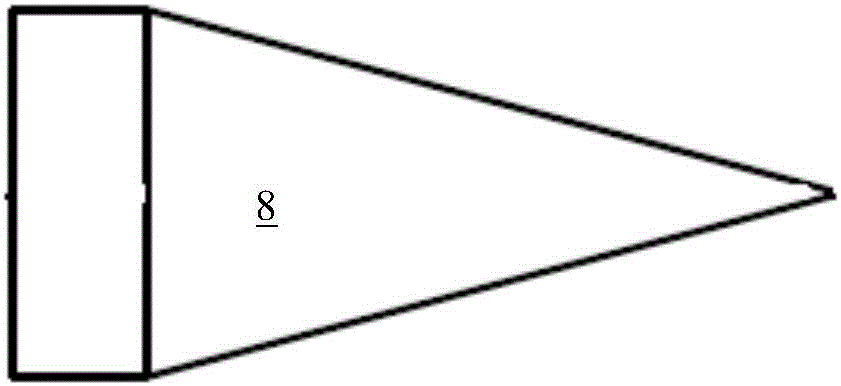
[0028] Such as Figure 1~4 Shown; A kind of manufacturing method of antenna absorbing load, described absorbing load 8 bottom surfaces are provided with threaded bottom hole 81, and it comprises the following steps:

[0029] S1. To study the material properties of carbonyl iron powder and the properties of the binder. The required binder material should have excellent mechanical strength, stiffness and hardness, and the high and low temperature resistance can reach -40℃~90℃. The material density and dielectric constant should be similar to the material properties of the epoxy resin selected for the original absorption load. Through the comparison of various alternative materials, the study decided to use polyamide PA6 (nylon) as the binder material, which has excellent mechanical strength, stiffness and hardness...


PUM


Abstract

The invention discloses a manufacturing method of an antenna absorption load. A thread bottom hole is formed in the bottom surface of the absorption load; and the manufacturing method comprises the following steps: (S1) carbonyl iron powder and polyamide PA6 are selected as injection raw materials; (S2) the mixture of carbonyl iron powder and polyamide PA6 is sampled and estimated; and the mean square error of the sample density is used for reflecting the uniformity of a feed for molding; (S3) according to influence on the injection blank performance by the process parameter change, parameters with maximum influence on the injection process and a no-defect injection area with changed injection parameters are found out; (S4) an injection mold is manufactured, and is connected with a metal molding injector; and (S5) the metal molding injector is used for injection molding of the feed estimated in the step (S2) according to the machining parameters in the step (S3) to obtain the absorption load part. The manufacturing method has the following advantages: the direct injection molding method for mixing high-grade engineering plastic with carbonyl iron powder according to a traditional design set ratio realizes once net molding of the absorption load, and largely increases the material utilization rate and the machining rejection rate.

Description

technical field [0001] The invention relates to the technical field of ultrafine metal powder processing, in particular to a method for manufacturing an antenna to absorb loads. Background technique [0002] With the rapid development of electronic technology, new requirements are put forward for magnetic materials. Magnetic components require complex shapes, miniaturization, high dimensional accuracy, high yield, low cost, and integration with other components. However, traditional powder metallurgy and Processing technology, the shape is limited, and the processing time is long and expensive. Among them, the absorbing load is used as a wave-absorbing element, which is widely used in antenna products of various models. The structural characteristics of this type of parts are sharp corners, cones, long strips, etc. The conventional molding process is to manually stir and cast the blank block. Milling cuts into strips and then grinds. This process takes a long time, consumes...

Claims


Application Information

Patent Timeline
Patent Type & Authority Applications(China)
IPC IPC(8): B29C45/00B29C45/26B29C45/78B29C45/77B29L31/34B29K77/00
CPCB29C45/00B29C45/2602B29C45/77B29C45/78B29C2945/76498B29C2945/76531B29C2945/76561B29K2077/00B29L2031/3456
Inventor 梁石陈路宋佳杰李凌铃徐洁芳
Owner SHANGHAI RADIO EQUIP RES INST
Why Eureka
Try Eureka