
Hemodialysis machine cleaning stick

A technology of hemodialysis machines and cleaning rods, applied in dialysis systems, suction equipment, etc., can solve the problems of wasting working time of medical staff, complex structure of cleaning rods, and many cleaning equipment, so as to avoid the risk of injury, eliminate welding procedures, The effect of improving the cleaning effect

Inactive Publication Date: 2017-05-10
TIANJIN SHITELEI BIOTECH
View PDF1 Cites 0 Cited by
  • Summary
  • Abstract
  • Description
  • Claims
  • Application Information

AI Technical Summary

Problems solved by technology

Using such a cleaning mode is cumbersome to operate due to the many connected cleaning devices, requiring medical staff to keep watch, wasting the working time of medical staff. There is an existing cleaning stick for hemodialysis machines, publication number CN204016960U, which overcomes the time-consuming cleaning of hemodialysis machines. , it is inconvenient to operate, and it needs medical staff to keep watch, which wastes the working time of medical staff. However, the structure of the cleaning rod is relatively complicated, with many parts and cumbersome assembly

Method used


Image

  • Hemodialysis machine cleaning stick
  • Hemodialysis machine cleaning stick
  • Hemodialysis machine cleaning stick

Examples


Embodiment Construction

[0016] The specific implementation, structure, features and effects provided by the present invention will be described in detail below in conjunction with the accompanying drawings and preferred embodiments.

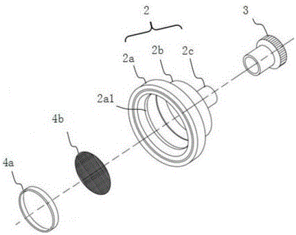
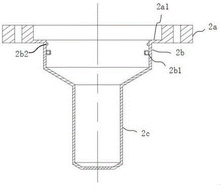
[0017] Such as figure 1 The shown cleaning stick of a hemodialysis machine comprises a cylindrical hollow tube body 1, the end of the tube body is welded in the first annular flange 2a at one end of the stepped connecting part 2, and the other end of the connecting part 2 The output port 2c is fastened to the end cap 3, the inner wall of the middle part of the connecting part 2 is provided with a second annular flange 2b, and the inner wall of the connecting part inside the second annular flange is provided with a plurality of ring-shaped ribs 2b2 , The filter membrane pressure ring 4a is clamped between the rib and the second annular flange, and a filter membrane 4b is arranged between the filter membrane pressure ring 4a and the second annular flange 2b.

[0018] The...


PUM


Abstract

The invention discloses a hemodialysis machine cleaning stick, which comprises a cylindrical hollow tube body. The end of the tube body is welded in a first annular flange at one end of a stepped connection part, and the output port at the other end of the connection part is buckled with an end cap. The inner wall of the middle part of the connection part is provided with a second annular flange, and the inner wall of the connection part on the inner side of the second annular flange is provided with a plurality of flanges arranged in a circle, wherein a filter membrane press ring is clamped between the flanges and the second annular flange, and a filter membrane is arranged between the filter membrane press ring and the second annular flange. Compared with the existing technology, the hemodialysis machine cleaning stick has prominent advantages and benefits. According to the hemodialysis machine cleaning stick, the structure is more convenient for assembling, the welding process of the filter is eliminated, the cleaning effect can be improved by a spoiler, the risk of misoperation can be avoided by the whole hermetic package, automatic dilution and automatic formulating are adopted, cleaning and disinfection can be completed at one time, high efficiency is realized, the material is environmentally sound, the space volume is small and the operation of medical staff is more convenient.

Description

technical field [0001] The invention relates to a cleaning device for a hemodialysis machine, in particular to a cleaning rod for a hemodialysis machine. Background technique [0002] After the hemodialysis machine is used, it needs to be cleaned, that is, the disinfectant sodium hypochlorite is put into the cleaning container, and the cleaning container is connected to the booster pump. Press the pump and start the cleaning mode. Using such a cleaning mode is cumbersome to operate due to the many connected cleaning devices, requiring medical staff to keep watch, wasting the working time of medical staff. There is an existing cleaning stick for hemodialysis machines, publication number CN204016960U, which overcomes the time-consuming cleaning of hemodialysis machines. , It is inconvenient to operate, and it needs medical staff to keep watch, which wastes the working time of medical staff. However, the structure of the cleaning rod is relatively complicated, with many parts ...

Claims


Application Information

Patent Timeline
Patent Type & Authority Applications(China)
IPC IPC(8): A61M1/16
CPCA61M1/168
Inventor 张磊靳蕾
Owner TIANJIN SHITELEI BIOTECH
Learn More