Eureka AIR delivers breakthrough ideas for toughest innovation challenges, trusted by R&D personnel around the world.

Element with pins and fixed to circuit board

A circuit board and component technology, which is applied in the direction of assembling printed circuits with electrical components, printed circuits connected with non-printed electrical components, etc., can solve the problem of inconvenient assembly, the side-to-side dumping of passive components 10a, and the time-consuming and expensive operation of assemblers. Work and other problems, to achieve the effect of easy welding process, good assembly stability and convenience, and avoid damage

Inactive Publication Date: 2013-01-30
DELTA ELECTRONICS INC
View PDF2 Cites 0 Cited by
  • Summary
  • Abstract
  • Description
  • Claims
  • Application Information

AI Technical Summary

Problems solved by technology

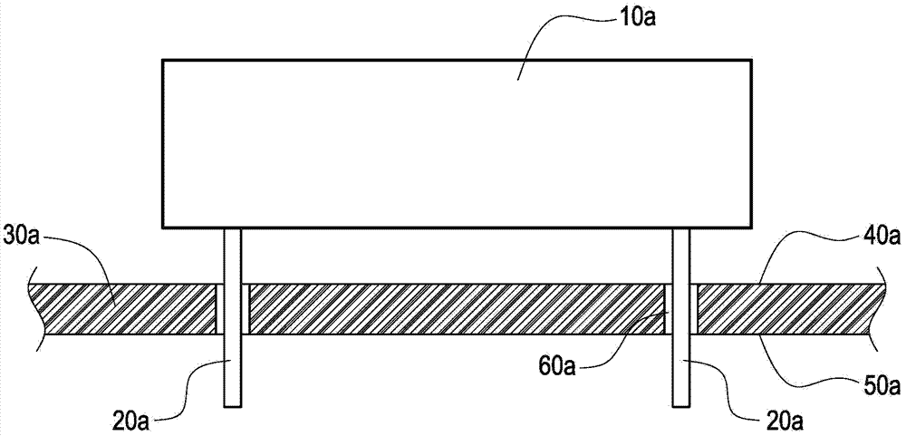
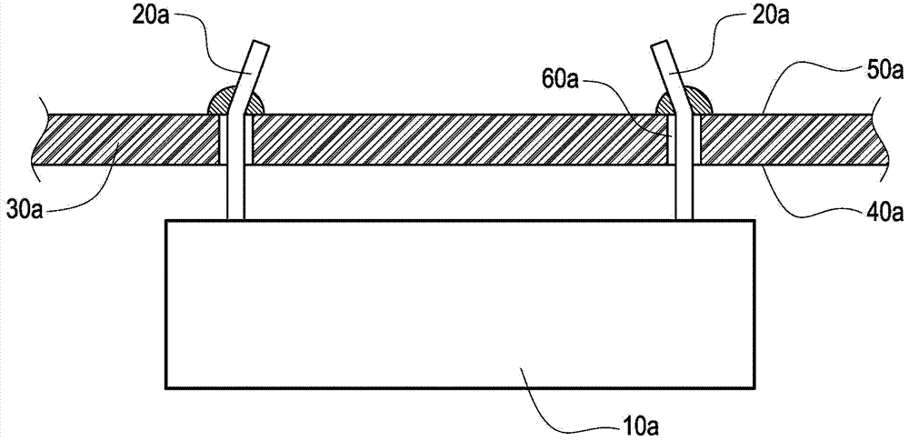
[0004] However, the above-mentioned passive component 10a only uses the upright legs 20a to penetrate the circuit board 30a, which causes the passive component 10a to fall left and right.
Therefore, in order to prevent the passive component 10a from falling to affect the assembly process, the assembler needs to arrange the soldering surface 50a of the circuit board 30a facing forward, and then install the passive component 10a on the circuit board 30a from the opposite placement surface 40a , and adjust the position of the passive component 10a from the bottom of the circuit board 30a, and then bend the upright leg 20a from the top of the circuit board 30a and solder to position the passive component 10a, but the adjustment orientation of the passive component 10a and the bending of the upright leg 20a The folding orientation is reversed, which often leads to a time-consuming and labor-intensive operation by the assembler, resulting in inconvenient assembly.

Method used


Image

  • Element with pins and fixed to circuit board
  • Element with pins and fixed to circuit board
  • Element with pins and fixed to circuit board

Examples


Embodiment Construction

[0061] The detailed description and technical content of the present invention will be described as follows with accompanying drawings, but the attached drawings are only for illustration purposes and are not intended to limit the present invention.

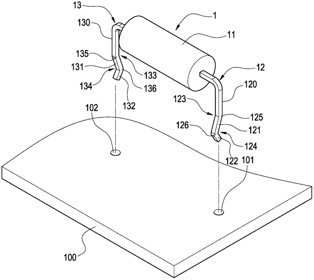
[0062] Please refer to Figure 3 to Figure 6 As shown, the present invention provides a component with pins fixed on the circuit board, the circuit board 100 is provided with a first through hole 101 and a second through hole 102, the first through hole 101 and the second through hole 102 have respectively An upright inner wall 103 and a bottom edge 104 .

[0063] A component with pins is a passive component 1, and the passive component 1 is a resistor, capacitor or inductor, such as image 3 As shown, it is the first embodiment of the component of the present invention. The component with pins is a resistor, but it is not limited thereto. The component with pins mainly includes a main body 11, a first pin 12 and a second Pin 1...


PUM


Abstract

The invention discloses an element with pins and fixed to a circuit board. The circuit board is provided with a first through hole and a second through hole. The element with pins comprises a body, a first pin and a second pin, the first pin is connected to one side of the body and comprises a first section, a first bent section and a second bent section, and the first bent section is penetratingly clamped in the first through hole. The second pin is connected to the other side of the body and comprises a second section, a third bent section and a fourth bent section, and the third bent section is penetratingly clamped in the second through hole. Therefore, the body is prevented from falling, and fine assembly stability and convenience can be achieved.

Description

technical field [0001] The invention relates to a component fixed on a circuit board, and in particular to a component with pins fixed on the circuit board. Background technique [0002] The circuit board is the substrate on which various parts are carried. The parts are active or passive electronic components and heat sinks to help the electronic components cool down. The circuit board is an insulator, and circuit lines are laid on the insulator. The components are connected to each other through the laid circuit, and the functions of various electronic components are played to achieve the purpose of signal processing. Therefore, in order to fix each part on the circuit board, the pins of the parts are directly soldered to the circuit. [0003] Please refer to figure 1 As shown, in the combination of the existing passive component 10a and the circuit board 30a, the two sides of the bottom end of the passive component 10a are respectively connected with mutually parallel v...

Claims


Application Information

Patent Timeline
IPC IPC(8): H05K1/18H05K3/30
Inventor 张永成
Owner DELTA ELECTRONICS INC
Why Eureka
Eureka Blog
Learn More