Roller brake

A technology of brakes and rollers, which is applied in the direction of hydraulic brakes, brake actuators, gear transmission mechanisms, etc., can solve the problem that the controllable braking of belt conveyors cannot be realized, the idler rollers do not have a braking function, and the safety of equipment is reduced and other problems, to achieve the effects of small braking impact, reliable braking, and controllable braking acceleration

Inactive Publication Date: 2017-05-03
于平
View PDF1 Cites 2 Cited by
  • Summary
  • Abstract
  • Description
  • Claims
  • Application Information

AI Technical Summary

Problems solved by technology

[0002] The belt conveyor is mainly composed of rollers, brackets, conveyor belt drive devices, etc. However, all kinds of rollers themselves do not have a braking function, and the conveyor needs to add a special brake to brake the equipment.
This concentrates the braking force and cannot realize the controllable braking of the belt conveyor, reducing the safety of the equipment

Method used


Image

  • Roller brake

Examples


Embodiment Construction

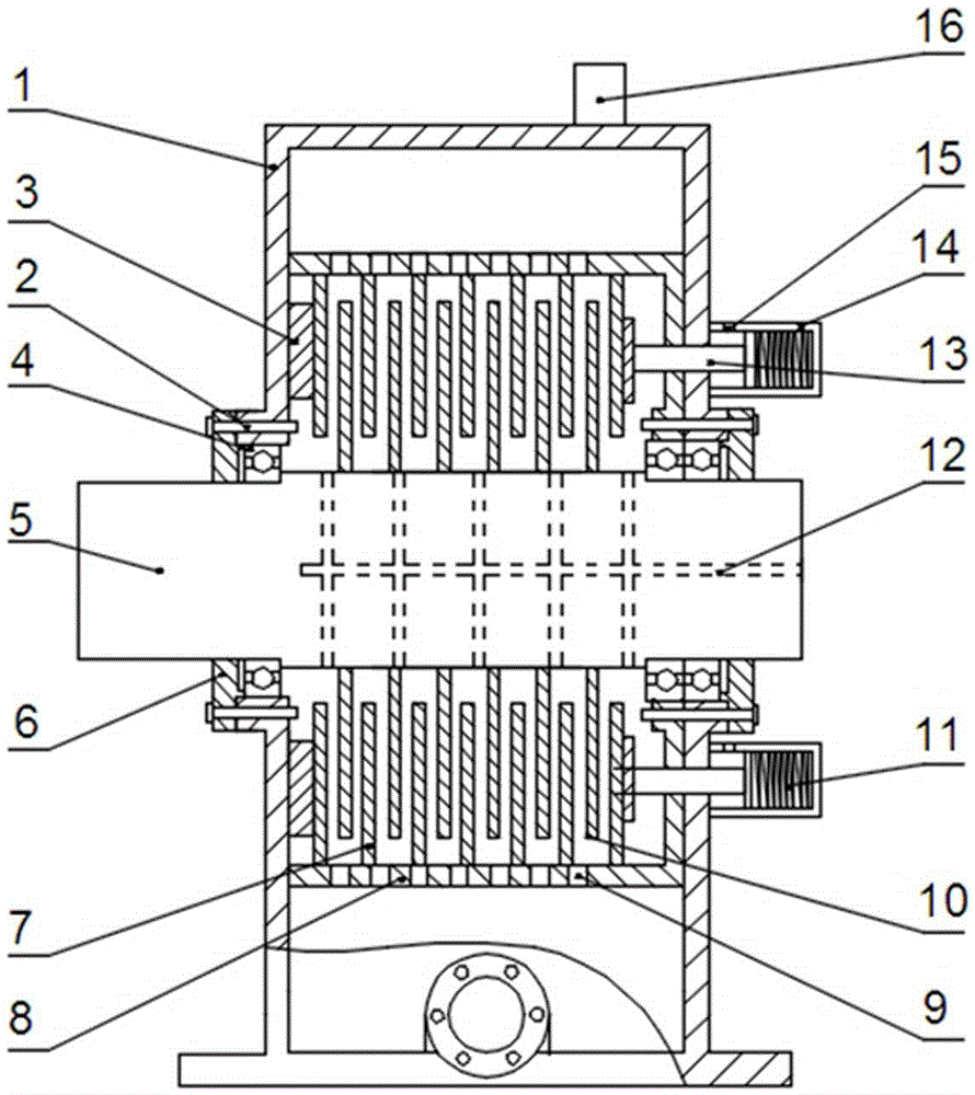
[0015] Roller brake, including box body, connecting bolts, backing plate, bearing, shaft, sealing cover, passive friction plate, passive drum, passive drum oil port, active friction plate, disc spring, brake oil passage, piston push rod, hydraulic red , Hydraulic red oil inlet and venting components.

[0016] The box is connected to the ground through anchor bolts; the brake oil passage is connected to the brake oil pump; the oil inlet of the hydraulic cylinder is connected to the control oil pump; the passive drum is connected to the box through bolts The two ends of the friction plate are made of powder metallurgy material, and oil grooves are arranged on it to facilitate the passage of brake oil and lubricate the cooling disc surface; the shaft is processed with axial oil passages and radial oil passages to make the brake oil It enters between the active and driven friction plates; a high-pressure sealing ring is installed between the sealing cover and the shaft to ensure t...


PUM


Abstract

The invention relates to a roller brake which comprises a box, a connecting bolt, a base plate, a bearing, a shaft, a sealing cover, a passive friction sheet, a passive drum, a passive drum oil opening, an active friction sheet, a disc spring, a brake oil way, a piston push rod, a hydraulic cylinder, a hydraulic cylinder oil inlet and a ventilation assembly. The box is connected with the ground through a foundation bolt; the brake oil way is connected with a brake oil pump; the hydraulic cylinder oil inlet is connected with a control oil pump; the passive drum is connected with the box; an axial oil way and a radial oil way are machined in the shaft, and a high-pressure sealing ring is arranged between the sealing cover and the shaft; outer teeth are arranged on the passive friction sheet and are connected with the passive drum; inner teeth are machined on the active friction sheet, and outer teeth are machined in the shaft matched with the active friction sheet; the hydraulic cylinder is designed outside the box; the active friction sheet and the passive friction sheet are installed in a spaced manner. The roller brake has the effects that the braking torque is stable, the braking impact is small, the braking accelerated speed is controllable, reliable braking is achieved when power is off suddenly, and power-off protection is achieved.

Description

technical field [0001] The invention relates to the field of material conveying equipment, in particular to a drum brake. Background technique [0002] The belt conveyor is mainly composed of rollers, brackets, conveyor belt drive devices, etc. However, all kinds of rollers themselves do not have a braking function, and the conveyor needs to add a special brake to brake the equipment. This concentrates the braking force and cannot realize the controllable braking of the belt conveyor, reducing the safety of the equipment. Traditional braking methods include mechanical friction braking, hydraulic braking, electrical braking, etc. This paper proposes a viscous brake for the drum, which uses the viscous shear force of the liquid to provide the braking torque. [0003] Chinese invention patent (application number: 201110140857.X application date: 2011-05-30) discloses a self-compensating controllable brake, including rollers, with pneumatic cylinders on both sides of the roller...

Claims


Application Information

Patent Timeline
IPC IPC(8): F16D55/40F16D65/14F16D121/06F16D121/24
Inventor 于平
Owner 于平
Why Eureka
Try Eureka