Critical liquid carrying condition optimization method in deep water gas well testing

An optimization method and gas well technology, applied in the field of exploration and development of oil and gas fields, can solve problems such as low accuracy, small pressure range, and small design results

Active Publication Date: 2017-04-26
CHINA NAT OFFSHORE OIL CORP +1
View PDF4 Cites 11 Cited by
  • Summary
  • Abstract
  • Description
  • Claims
  • Application Information

AI Technical Summary

Problems solved by technology

However, in the testing process of deep-water gas wells, due to the large range of pressure and temperature changes in the wellbore, it is easy to cause a large amount of condensate to precipitate. It is easy to cause the risk of failure in the field test operation
For the calculation of natural gas high-pressure physical property parameters and the prediction of critical liquid-carrying flow conditions, although there are relatively mature commercial software PIPESIM (multiphase flow steady-state simulation software) and WELLFLO (hydraulic simulation software) in foreign countries, PIPESIM and WELLFLO software are used for natural gas The calculation of high-pressure physical parameters and the prediction of critical liquid-carrying flow conditions usually have the following disadvantages: First, the calculation of natural gas high-pressure physical The fixed-value drag coefficient Turner model predicts the critical liquid-carrying flow conditions of the entire well section, which makes the design result too small, which makes it impossible to make a reasonable judgment on the liquid-carrying situation of the entire well section of the deepwater gas well

Method used


Image

  • Critical liquid carrying condition optimization method in deep water gas well testing
  • Critical liquid carrying condition optimization method in deep water gas well testing
  • Critical liquid carrying condition optimization method in deep water gas well testing

Examples


Embodiment Construction

[0071] The present invention will be described in detail below in conjunction with the accompanying drawings and embodiments.

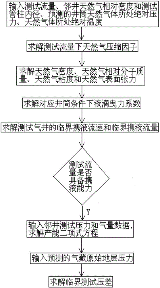
[0072] Such as figure 1 As shown, the deep-water gas well test critical liquid-carrying condition optimization method proposed by the present invention comprises the following steps:

[0073] 1) Determine the test flow rate of the wellbore, and calculate the natural gas compression factor at each point in the wellbore according to the relative density of natural gas in the adjacent well and the inner diameter of the test string, as well as the predicted absolute pressure and temperature of the natural gas in the wellbore. Then calculate the natural gas density, natural gas relative molecular mass, natural gas viscosity and natural gas surface tension at the corresponding points in the wellbore according to the obtained natural gas compression factors at each point in the wellbore, and use the obtained natural gas viscosity to determine the liquid drop...


PUM


Abstract

The present invention relates to a critical liquid carrying condition optimization method in deep water gas well testing. The method is characterized by comprising a first step of determining a test flow of a wellbore, calculating a natural gas compression factor of each point in the wellbore according to a natural gas relative density of an adjacent well and internal diameter data of a test pipe, a predicted absolute pressure of wellbore natural gas, and an absolute temperature of the natural gas, next, calculating natural gas density, natural gas relative molecular mass, natural gas viscosity and natural gas surface stress of a corresponding point in the wellbore according to the acquired natural gas compression factor of each point in the wellbore, and determining a drag force for carrying the drop to be out of the well of each point in the wellbore by using the acquired natural gas viscosity; a second step of calculating a critical liquid carrying flow rate and a critical liquid carrying flow in deep water gas well testing; and a third step of calculating a bottom flow pressure corresponding to the critical liquid carrying flow in deep water gas well testing according to test pressure and gas quantity data of the adjacent well, and calculating a critical test pressure difference required in deep water gas well testing by using the bottom flow pressure.

Description

technical field [0001] The invention relates to a method for optimizing critical liquid-carrying conditions in deep-water gas well testing, and belongs to the technical field of oil and gas field exploration and development. Background technique [0002] Deepwater testing is an important link in deepwater oil and gas exploration and development, and it is also the most direct means to obtain formation physical parameters and boundary conditions. During deep-water gas well testing, if the test fluid cushion and induced blowout fluid cushion cannot be completely flowed back from the bottom of the well during the well-cleaning stage, it will cause pollution to the gas reservoir, resulting in failure to obtain fluid samples for deep-water testing. During the blowout stage of the deep water test, the pressure and temperature in the wellbore decrease, resulting in a large amount of condensate precipitation, which is easy to form liquid accumulation at the bottom of the well, there...

Claims


Application Information

Patent Timeline
IPC IPC(8): G06Q50/02
CPCG06Q50/02
Inventor 李紫晗何玉发高飞
Owner CHINA NAT OFFSHORE OIL CORP
Why Eureka
Try Eureka