
Illuminating lamp fixture serving as tool

A lamp and tooling technology, applied in the field of lighting tooling lamps, can solve the problems of difficult acceptance and delivery, long delivery cycle, high cost, etc., and achieve the effects of shortening the delivery cycle, prolonging the service life and reducing costs

Active Publication Date: 2017-04-26
SHANGHAI WAIGAOQIAO SHIP BUILDING CO LTD
View PDF2 Cites 3 Cited by
  • Summary
  • Abstract
  • Description
  • Claims
  • Application Information

AI Technical Summary

Problems solved by technology

[0004] The technical problem to be solved by the present invention is to provide a lighting fixture for overcoming the defects of the prior art, such as difficulties in acceptance and delivery, huge cost, and long delivery period.

Method used


Image

  • Illuminating lamp fixture serving as tool
  • Illuminating lamp fixture serving as tool
  • Illuminating lamp fixture serving as tool

Examples


Embodiment 1

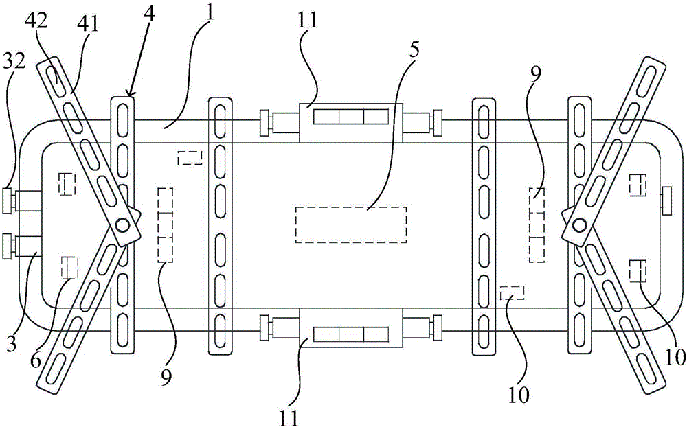
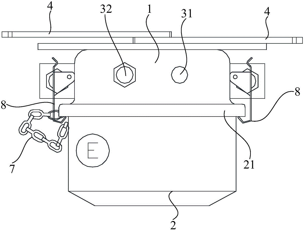
[0067] like figure 1 and figure 2 As shown, the lighting fixture of the present invention includes a housing 1, a lampshade 2, several wire inlets 3, at least one ballast 5, and at least one lamp holder 6. The bottom of the housing 1 is detachably connected to The lampshade 2, and the housing 1 and the lampshade 2 form a cavity, the wire inlet 3 is located on the outer surface of the housing 1, the wire inlet 3 includes a wire inlet 31, a stuffing box (not shown in the figure), and the wire inlet Port 31 is sleeved in the stuffing box, and the stuffing box is connected with the cavity, and the external cable enters the cavity through the stuffing box to completely cover and protect the internal components. According to the lighting layout requirements of ships or offshore platforms, the type of lamps can be selected, and the combination of incoming and outgoing lines of the lighting circuit can be selected through the incoming line part 3. It can be divided into alternative...

Embodiment 2

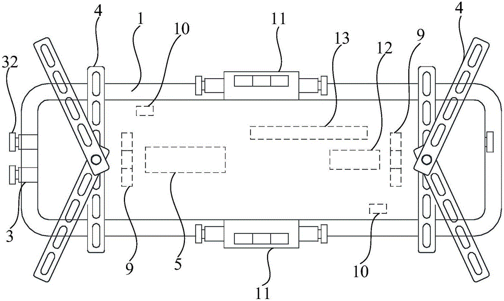
[0079] like image 3 and Figure 4 As shown, the structure of the lighting fixture of this embodiment is the same as that of Embodiment 1 and will not be repeated, only the differences will be described. The lighting tool lamp includes an automatic charging and discharging device, which is electrically connected to the ballast 5. When the external power supply is interrupted, it will automatically provide power to the lamp for continuous lighting as an emergency escape lighting function.

[0080] The automatic charging and discharging device includes a storage battery 13 and an inverter 12, and the two ends of the inverter 12 are electrically connected to the storage battery 13 and the ballast 5 respectively. The battery 13 is used to provide power, and the inverter 12 uses the power provided by the battery 13 to meet the requirements of the lamp. Preferably, the storage battery 13 is a lithium-ion battery pack or a nickel-cadmium battery pack, and the lithium-ion battery pa...

Embodiment 3

[0083] like Figure 5 and Figure 6 As shown, the structure of the lighting fixture of this embodiment is the same as that of Embodiment 1 and will not be repeated, only the differences will be described. The adjustable mounting hole distance device 4 includes a number of through holes 43 which are connected to the cavity. The through holes 43 are provided on the top of the housing 1 without additional materials. The structure is simple and the cost is low. The through holes 43 are fixedly connected to the lighting fixtures by bolts, so that the lighting fixtures are easy to assemble and disassemble.


PUM


Abstract

The invention discloses an illuminating lamp fixture serving as a tool. The illuminating lamp fixture comprises a shell, a lamp shade, multiple wire inlet portions, one or more ballast resistors and one or more lamp holders. The two ends of the top of the shell are each provided with an adjustable mounting hole pitch device. The bottom of the shell is detachably connected to the lamp shade, and a cavity is formed by the shell and the lamp shade. The wire inlet portions are located on the outer surface of the shell, and each wire inlet portion comprises a wire inlet opening and a stuffing box. Each wire inlet opening is formed in the corresponding stuffing box in a sleeved manner. The stuffing boxes communicate with the cavity. The ballast resistors are located in the cavity. The lamp holders are connected into the shell and electrically connected to the lamp holders. By means of the illuminating lamp fixture serving as the tool, the mounting requirement of different hole pitches can be met; and in addition, the service life of each interior element can be prolonged. Meanwhile, the illuminating lamp fixture can be substituted to be applied, so that the multifunctional use requirement is met. Unnecessary losses are lowered to the minimum; testing and acceptance inspection pressure generated in the building process of a ship or ocean platform is greatly lowered; cost is lowered; and the delivery cycle is greatly shortened.

Description

technical field [0001] The invention relates to a lighting tool lamp. Background technique [0002] Over the past ten years, China's shipbuilding industry has occupied a higher and higher proportion in the global market, and has gradually become an important shipbuilding center in the world. Among them, the marine engineering equipment industry is a strategic emerging industry that my country is currently accelerating its cultivation and development. It is an important direction for the adjustment and revitalization of the traditional shipbuilding industry, especially the construction of offshore oil drilling platforms. For the construction of offshore oil drilling platforms, the common situation at home and abroad is that the construction period is long, the construction environment is harsh, and the equipment acceptance assessment is strict. Taking the JU2000E emergency lighting fixtures for offshore platforms as an example, the number of emergency lighting fixtures per sh...

Claims


Application Information

Patent Timeline
IPC IPC(8): F21S9/02F21V23/00F21V23/02F21V21/00F21V17/16F21V7/00F21V23/06F21Y115/10
CPCF21S9/02F21V7/00F21V17/164F21V21/00F21V23/001F21V23/02F21V23/06
Inventor 袁飞晖张学辉于栋亮陈霖杨雪莲
Owner SHANGHAI WAIGAOQIAO SHIP BUILDING CO LTD
Learn More