
Household intelligent ultraviolet lamp

An ultraviolet lamp, intelligent technology, applied in sanitary equipment for toilets, water supply devices, buildings, etc., can solve the problems of DNA structure damage, incomplete disinfection, human injury, etc., and achieves good safety performance, simple structure, and convenient control. Effect

Pending Publication Date: 2017-03-29
TIANJIN GUANGZE NOBLELIGHT CO LTD
View PDF7 Cites 4 Cited by
  • Summary
  • Abstract
  • Description
  • Claims
  • Application Information

AI Technical Summary

Problems solved by technology

[0002] With the deteriorating environment and climate, more and more people and animals are in sub-health, and the diet and life of all aspects of human beings are in an abnormal state. Therefore, the use of ultraviolet rays to disinfect, sterilize, purify humans, animals and the environment has become the first choice for people. Ultraviolet rays Disinfection began with the invention of the first ultraviolet germicidal lamp by Dr. Heraeus in Germany. Ultraviolet germicidal technology has been widely used in more and more fields, especially in air sterilization, object surface sterilization, and water treatment sterilization. The scientific principle of ultraviolet disinfection: it mainly acts on the DNA of microorganisms, destroys the DNA structure, and makes them lose the function of reproduction and self-replication so as to achieve the purpose of sterilization and disinfection. Disinfection lamps can only locally sterilize objects or harmful substances in the air, resulting in incomplete disinfection. In addition, ultraviolet rays can also cause harm to the human body and even cause cancer

Method used


Image

  • Household intelligent ultraviolet lamp

Examples


Embodiment Construction

[0014] The technical solutions in the embodiments of the present invention will be clearly and completely described below in conjunction with the accompanying drawings in the embodiments of the present invention. Obviously, the described embodiments are only a part of the embodiments of the present invention, rather than all the embodiments. Based on the embodiments of the present invention, all other embodiments obtained by those of ordinary skill in the art without creative work shall fall within the protection scope of the present invention.

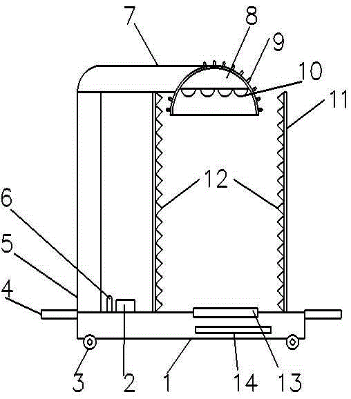
[0015] See figure 1 In the embodiment of the present invention, the home smart ultraviolet lamp is characterized by a base (1), a controller (2), a roller (3), a carrying handle (4), a support column (5), and a signal receiver ( 6) Crossbar (7), lampshade (8), heat sink (9), ultraviolet tube (10), reflector (11), photocatalyst coating (12), fan (13) and infrared sensor (14) ) Composition; the bottom of the base (1) is provided with a ro...


PUM


Abstract

The invention discloses a household intelligent ultraviolet lamp. The household intelligent ultraviolet lamp is characterized in that rollers are arranged at the bottom of a base; a supporting post is arranged at the upper left end of the base; a transverse rod is arranged at the upper end of the supporting post; a lampshade is arranged at the tail end of the transverse rod; an ultraviolet lamp tube is arranged in the lampshade; a plurality of cooling strips are arranged on the outer side of the lampshade at equal intervals; a fan is arranged in the position, on the right side of the supporting post, of the base; parallel light reflection mirrors are arranged around the fan, and the inner side of each light reflection mirror is coated with a photocatalyst coating; a controller is arranged in the position, close to the supporting post, of the base, and the controller is provided with a signal receiver; and an infrared inductor is arranged on the front side of the base. The light reflection mirrors can gather ultraviolet light in the space defined by the light reflection mirrors, and human bodies are protected against irradiation of the ultraviolet light while the air sterilization efficiency can be effectively improved. The photocatalyst coatings can purify air. The fan can blow sterilized or purified air to the outside, so that air in a house circulates, and large-area sterilization or purification of indoor air is achieved. Thus, the air quality is greatly improved.

Description

Technical field [0001] The invention relates to a disinfection device, in particular to a household intelligent ultraviolet lamp. Background technique [0002] With the deteriorating environmental climate, more and more humans and animals are in sub-health. All aspects of human diet and life are in an abnormal state. Therefore, the use of ultraviolet disinfection, sterilization, purification of humans and animals and the environment has become the first choice of people. Disinfection started with the invention of the first UV germicidal lamp by Dr. Heraeus in Germany. UV germicidal technology has been widely used in more and more fields, especially in air sterilization, object surface sterilization, and water treatment sterilization. The scientific principle of ultraviolet disinfection: It mainly acts on the DNA of microorganisms, destroys the DNA structure, and makes it lose the function of reproduction and self-replication, so as to achieve the purpose of sterilization. Ultravi...

Claims


Application Information

Patent Timeline
IPC IPC(8): A61L2/10A61L2/24A61L9/20
Inventor 李海滨
Owner TIANJIN GUANGZE NOBLELIGHT CO LTD
Learn More