UV led packaging method

A LED packaging and LED chip technology, applied in semiconductor devices, electrical components, circuits, etc., can solve problems affecting chip performance, loss of sealing performance, and easy aging of materials, so as to achieve uniform protective film, prolong sealing time, and improve cleanliness Effect

Active Publication Date: 2019-03-05
QINGDAO JASON ELECTRIC
View PDF10 Cites 0 Cited by
  • Summary
  • Abstract
  • Description
  • Claims
  • Application Information

AI Technical Summary

Problems solved by technology

[0004] In order to solve the technical problem that the material used in the existing ultraviolet LED packaging method is easy to age, and the loss of sealing performance directly affects the performance of the chip, a kind of ultraviolet LED packaging method is proposed, which can solve the above problems

Method used


Image

  • UV led packaging method
  • UV led packaging method
  • UV led packaging method

Examples


Embodiment 1

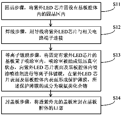
[0034] This embodiment proposes a method for packaging ultraviolet LEDs, such as figure 1 shown, including the following steps:

[0035] S11, the crystal-bonding step, fixing the ultraviolet LED chip in the crystal-bonding area in the cavity of the substrate;

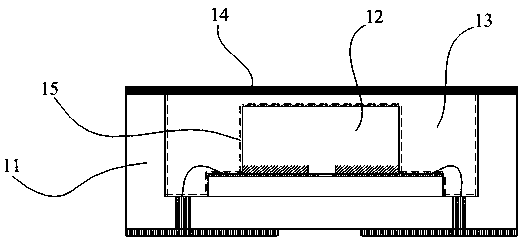
[0036] This embodiment adopts chip-on-board packaging technology, such as figure 2 As shown, a substrate 11 is included, and a cavity 13 for accommodating a chip 12 is provided on the substrate 11 .

[0037] S12, wire bonding step, connect the ultraviolet LED chip to the relevant circuit terminal with a wire;

[0038] S13, plasma coating step, place the substrate with the UV LED chip fixed in the spraying chamber, the spraying chamber is pumped into a low-pressure vacuum state, spray the spraying agent on the surface of the UV LED chip and the cavity of the substrate for plasma coating, and place the substrate on the surface of the UV LED chip And a protective film is formed on the inner surface of the substrate cav...

Embodiment 2

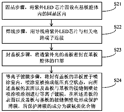
[0049] This embodiment proposes another UV LED packaging method, such as image 3 shown, including the following steps:

[0050] S21, the crystal-bonding step, fixing the ultraviolet LED chip in the crystal-bonding area in the cavity of the substrate;

[0051] This embodiment adopts chip-on-board packaging technology, such as Figure 4 As shown, a substrate 11 is included, and a cavity 13 for accommodating a chip 12 is provided on the substrate 11 .

[0052] S22, wire bonding step, connect the ultraviolet LED chip to the relevant circuit terminal with a wire;

[0053] S23 , the step of sealing the cover plate, sealing the cover plate transparent to the ultraviolet light on the mouth of the substrate cavity.

[0054] S24, plasma coating step, place the substrate sealed with the cover plate in the spraying chamber, the spraying chamber is pumped into a low-pressure vacuum state, and spray the spraying agent on the surface of the cover plate and the joint side wall of the cove...


PUM


Abstract

The invention discloses a method for packaging ultraviolet LEDs, which includes the following steps: (11), a crystal-bonding step, fixing an ultraviolet LED chip in a crystal-bonding area in a cavity of a substrate; (12), a wire bonding step, using wires to The ultraviolet LED chip is connected to the relevant circuit terminal; (13), the plasma coating step, the substrate fixed with the ultraviolet LED chip is placed in the spraying room, and the spraying room is pumped into a low-pressure vacuum state, and the plasma is applied to the surface of the ultraviolet LED chip and the substrate cavity. Coating; (14), the step of sealing the cover plate, sealing the cover plate transparent to ultraviolet light on the mouth of the substrate cavity. The ultraviolet LED packaging method of the present invention can add another layer of protective film to the ultraviolet LED chip, which can delay the aging of the cover plate and prolong the sealing time of the cover plate. The mouth of the substrate cavity is sealed by a UV-transmissive cover plate, which avoids the problem of poor UV resistance of epoxy resin or silica gel and low light extraction efficiency.

Description

technical field [0001] The invention belongs to the technical field of semiconductor encapsulation, and in particular relates to an ultraviolet LED encapsulation method. Background technique [0002] There are two main forms of UV LED bare chip packaging technology: one is Chip On Board (COB) technology, and the other is flip chip technology. As far as the COB process is concerned, the semiconductor chip is handed over and mounted on the substrate through the crystal-bonding process, and then electrically connected between the chip and the substrate by wire bonding, and finally poured on the chip with resin. The surface of the chip and bracket is covered and then cured to complete the package. The connection between the commonly used epoxy resin or silica gel and the LED chip or substrate is easy to crack due to aging and other reasons after long-term use, resulting in loss of sealing performance, and the outside air directly contacts the chip. , affecting the performance o...

Claims


Application Information

Patent Timeline
Patent Type & Authority Patents(China)
IPC IPC(8): H01L33/00H01L33/48H01L33/54H01L33/62
CPCH01L33/005H01L33/48H01L33/54H01L33/62H01L2933/0066H01L2933/005H01L2924/16195H01L2224/16145H01L2224/48091H01L2224/48227H01L2924/00014
Inventor 白生茂曲丞世张晓裴潘娜王洁武帅周德保梁旭东
Owner QINGDAO JASON ELECTRIC
Why Eureka
Try Eureka