Tool for whirlwind milling of square shaft

A whirling milling and cutting tool technology, which is applied in the direction of milling cutters, manufacturing tools, milling machine equipment, etc., can solve the problems of increasing the instability of processing dimensions, poor rigidity of the process system, and the inability to use the follower tool holder, etc., so as to improve the processing accuracy and Surface quality, extended tool life, avoiding back-off effects

Inactive Publication Date: 2017-03-22
SHIMGE PUMP IND GRP CO LTD
View PDF9 Cites 1 Cited by
  • Summary
  • Abstract
  • Description
  • Claims
  • Application Information

AI Technical Summary

Problems solved by technology

There are problems with this processing method: the surface after rough machining is no longer cylindrical, and the tool holder cannot be used during finishing, the rigidity of the process system becomes worse, the machining accuracy is reduced instead, and the milling efficiency is doubled; There is also the radial repetitive positioning error caused by the radial feed of the machine tool, which increases the instability of the processing size

Method used


Image

  • Tool for whirlwind milling of square shaft
  • Tool for whirlwind milling of square shaft
  • Tool for whirlwind milling of square shaft

Examples


Embodiment

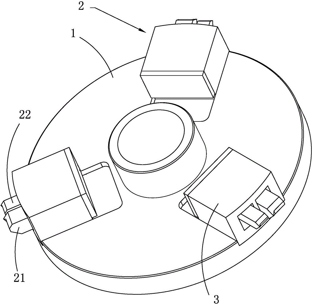
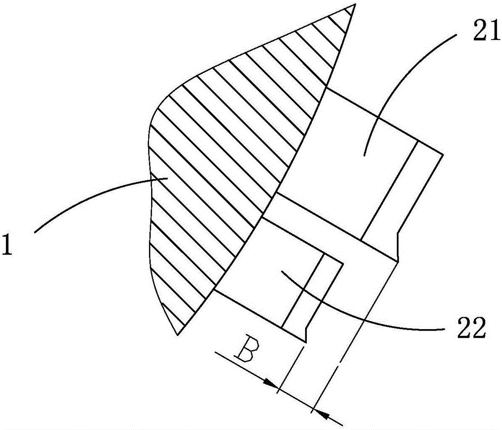
[0030] Example: A tool for whirling a square shaft, such as figure 1 As shown, it includes a disk body 1, which is arranged on the disk body, and a pair of cutting knives 2 are respectively installed at the positions of equal parts of the circumference. The cutting knives are radially distributed with the center of the disk body as the center. The part is located outside the disc body. Each pair of said cutting blades has two cutter bodies arranged side by side, which are respectively a roughing blade 21 and a finishing blade 22. edge distance.

[0031] The cutting knife pair on each part of the disc body has two cutting knives, one for rough machining and one for finish machining. There is no need for repositioning, avoiding errors caused by repositioning and affecting machining errors. At the same time, the tool holder can always be used, which not only improves the machining accuracy, but also improves the machining efficiency. Since each processing surface has been pro...


PUM


Abstract

The invention relates to a tool for whirlwind milling of a square shaft. By adoption of the tool for whirlwind milling of the square shaft, the problem of two-round successive milling including a round of rough machining and a subsequent round of finish machining in the prior art is solved. According to the technical scheme, the tool for whirlwind milling of the square shaft comprises a disc body; cutting tools are arranged on the disc body, each circumferential equipartition point is provided with one cutting tool, and the cutting tools are distributed in a radial shape with the center of the disc body as the center; and the blade portion of each cutting tool is located outside the disc body. The tool for whirlwind milling of the square shaft is characterized in that each cutting tool is provided with two tool bodies, namely the rough machining tool body and the finish machining tool body, which are arranged side by side, and the distance from the blade portion of each rough machining tool body to the edge of the disc body is smaller than the distance from the blade portion of the corresponding finish machining tool body to the edge of the disc body. The tool for whirlwind milling of the square shaft has the effects that since the rough machining tool body and the finish machining tool body of each cutting tool are arranged in the front-back direction, rough machining and finishing machining are conducted continuously, using of follow rests is not affected, and workpieces can be supported by the follow rests; and the rigidity of a system can be maintained, and the machining precision can be ensured easily.

Description

technical field [0001] The invention relates to a cutter for whirling a square shaft, in particular to a cutter for whirling a square shaft in which each pair of cutting knives has two cutters. Background technique [0002] For shaft parts, it is often necessary to locally process them into square shafts (including two or more regular polyhedral shafts, the following uses a common hexahedron as an example to describe the principle). If the square shaft structure is longer, it is often processed by the whirling milling process with high processing efficiency and stable hexagonal division accuracy. [0003] The whirling milling tool includes a disc body, on which a tool is installed in the radial direction at equally divided positions on the circumference. During milling, the disc body and the spindle of the machine tool rotate in the same direction at a certain speed ratio, the disc body moves relative to the shaft blank, and the tool cuts figure 2 image 3 The shaded part...

Claims


Application Information

Patent Timeline
Patent Type & Authority Applications(China)
IPC IPC(8): B23C5/08
CPCB23C5/08
Inventor 杨岩松葛杰凌桂荣
Owner SHIMGE PUMP IND GRP CO LTD
Why Eureka
Try Eureka