Special machine tool for roller boring

A special machine tool and roller technology, applied in the field of machine tools, can solve the problems of inability to guarantee the accuracy of boring holes, not meeting the requirements of low cost, and low machining accuracy, and achieve the effects of obvious industrial application value, low noise and low cost.

Inactive Publication Date: 2017-03-22
SHANGHAI UNIV OF ENG SCI
View PDF8 Cites 1 Cited by
  • Summary
  • Abstract
  • Description
  • Claims
  • Application Information

AI Technical Summary

Problems solved by technology

[0003] As the carding machine is more widely used in the textile industry, the production and processing of the key parts of the carding machine, the cylinder roller and the doffer roller, has become mass production. However, for the boring of the large diameter cylinder roller and the doffer roller Hole processing on ordinary boring machines cannot guarantee the boring accuracy, the machining accuracy of the holes is not high, and the labor intensity is high, and the processing efficiency is low; while using modern intelligent machine tools, there is a problem of high cost, which does not meet the requirements of low cost

Method used


Image

  • Special machine tool for roller boring
  • Special machine tool for roller boring

Examples


Embodiment

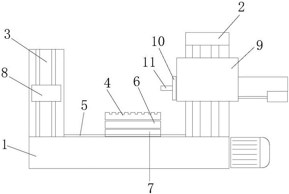
[0018] like figure 1 As shown: a special machine tool for boring roller holes provided by the present invention is an improved horizontal boring machine, including a bed 1, and the bed 1 is provided with a front column 2, a rear column 3 and a workbench 4, The workbench 4 is located between the front column 2 and the rear column 3, and the bed 1 is provided with an axial slideway 5 at a position connected to the rear column and the worktable surface. An upper slide seat 6 and a lower slide seat 7 are provided in sequence, the workbench 4 is arranged on the axial slideway 5 of the bed 1, and the workbench 4 and the bed 1 form a moving pair, and the rear column 3 is set On the axial slideway 5 and form a moving pair with the bed 1, a vertical slide rail is arranged on the rear column 3, and a rear support frame 8 is installed on the vertical slide rail of the rear column. There is a vertical slide rail, and a headstock 9 is installed on the vertical slide rail of the front colu...

Embodiment approach

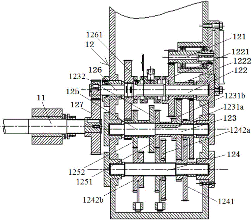
[0020] One embodiment, the input transmission shaft 122 is provided with a large transmission gear 1221 and a transmission pinion 1222, and the primary transmission shaft 123 is provided with two sets of transmission gear sets 1231a, 1231b and a transmission gear 1232, A transmission gear set 1241 and two sets of sliding gear sets 1242a, 1242b are provided on the two-stage transmission shaft 124, a transmission gear 1251 and a transmission gear set 1252 are set on the output transmission shaft 125, and the output shaft 126 The upper sleeve is provided with a transmission gear 1261; and, the transmission bull gear 1221 on the input transmission shaft 122 is meshed with the input shaft 121 to form two sets of transmission gear sets 1231a, 1231b on the primary transmission shaft 123. The bull gears are all connected to the input The small gears on the transmission shaft 122 are meshed and connected, and the large gears forming the transmission gear set 1241 on the secondary speed ...


PUM


Abstract

The invention discloses a special machine tool for roller boring, and the special machine tool is an improved horizontal boring mill. The special machine tool comprises a lathe bed. The lathe bed is provided with a front stand column, a rear stand column and a workbench. An upper sliding base and a lower sliding base are sequentially arranged below the workbench. A main shaft box is arranged on the front stand column. A rear supporting frame is arranged on the rear stand column. A facing head is arranged on the end face of the main shaft box. The main shaft box is internally provided with a speed change transmission structure used for driving the movement of a main shaft. An output shaft of the speed change transmission structure is in transmission connection with the main shaft. The speed change transmission structure comprises an input shaft, an input transmission shaft, a first-level speed change shaft, a second-level speed change shaft, an output transmission shaft and the output shaft. The input shaft is in transmission connection with an outside power output shaft, the input transmission shaft is in transmission connection with the input shaft, the first-level speed change shaft is in transmission connection with the input transmission shaft, the second-level speed change shaft is in transmission connection with the first-level speed change shaft and the output transmission shaft, and the output transmission shaft is in transmission connection with the output shaft. The special machine tool can guarantee boring machining precision and also has the beneficial effects of being simple in structure, low in noise and the like.

Description

technical field [0001] The invention relates to a special machine tool for boring roller holes, which belongs to the technical field of machine tools. Background technique [0002] A special-purpose machine tool is a machine tool that is specially suitable for processing a specific part or a specific process. Because special-purpose machine tools generally have the advantages of low cost, high efficiency and high quality, they are widely used in mass production. [0003] As the carding machine is more widely used in the textile industry, the production and processing of the key parts of the carding machine, the cylinder roller and the doffer roller, has become mass production. However, for the boring of the large diameter cylinder roller and the doffer roller Hole processing on ordinary boring machines cannot guarantee the boring accuracy, the hole processing accuracy is not high, and the labor intensity is high, and the processing efficiency is low; while using modern inte...

Claims


Application Information

Patent Timeline
Patent Type & Authority Applications(China)
IPC IPC(8): B23B41/00B23B47/14
CPCB23B41/00B23Q5/12B23Q2705/062
Inventor 高瞩柏杰
Owner SHANGHAI UNIV OF ENG SCI
Why Eureka
Try Eureka