
Photoelectric detector frequency response measurement method and measurement system thereof

A technology of photodetector and frequency response, which is applied in the direction of frequency measurement devices, etc., can solve the problems of time-domain method bandwidth limitation, etc., and achieve the effects of high test efficiency, high measurement accuracy and high measurement accuracy

Active Publication Date: 2017-03-15
NANJING UNIV OF AERONAUTICS & ASTRONAUTICS
View PDF6 Cites 9 Cited by
  • Summary
  • Abstract
  • Description
  • Claims
  • Application Information

AI Technical Summary

Problems solved by technology

[0004] The key device for time-domain method to measure the frequency response of photodetectors is sampling oscilloscope, but the limitation of time-domain method is that the frequency range of measuring photodetectors is limited by the bandwidth of sampling oscilloscopes

Method used


Image

  • Photoelectric detector frequency response measurement method and measurement system thereof
  • Photoelectric detector frequency response measurement method and measurement system thereof
  • Photoelectric detector frequency response measurement method and measurement system thereof

Examples


Embodiment Construction

[0028] Below in conjunction with the accompanying drawings and specific embodiments, the technical solutions of the present invention are described in further detail:

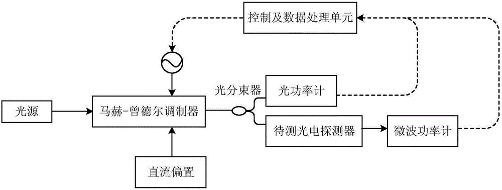
[0029] The present invention is a photodetector frequency response measurement system, such as figure 1 As shown, it includes: a light source, a microwave source, a DC bias module, an intensity modulator, an optical beam splitter, an optical power meter, a microwave power meter, and a control and data processing unit. The idea of ​​the present invention is to use an intensity modulator to modulate the microwave signal output by the microwave source to the optical carrier output by the light source to generate an optical double-sideband detection signal; the optical beam splitter divides the optical double-sideband detection signal into two channels, and one channel outputs light. The power meter detects the power of the double-sideband detection signal of the light, and the other input is the photodetector to b...


PUM


Abstract

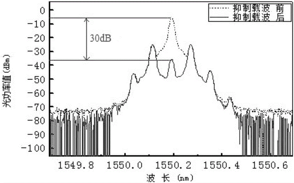
The invention discloses a photoelectric detector frequency response measurement method and a measurement system thereof and belongs to the photoelectric device measurement and microwave photonics technology field. In the invention, an intensity modulator is adopted to modulate a microwave signal to a optical carrier wave, after proper direct current bias, an optical double-sideband detecting signal which restrains the carrier wave is generated. An optical beam splitter divides an optical signal into two paths. One path of the optical signal is input into an optical power meter so as to detect optical power and the other path of the optical signal is input into a photoelectric detector to be measured. A microwave power meter measures power of a microwave signal output by the photoelectric detector to be measured. Frequency scanning is performed on the microwave signal so that changing curves of optical power of an optical detection signal and microwave signal power output by the photoelectric detector along with frequencies can be acquired. According to a photoelectric detector frequency response definition, a frequency response curve of the photoelectric detector to be measured can be acquired. The invention also discloses a photoelectric detector frequency response measurement system. Compared to the prior art, a measurement range is expanded and measurement precision and efficiency are increased.

Description

technical field [0001] The invention relates to a photodetector frequency response measurement method and measurement system, in particular to a photodetector frequency response measurement method and measurement device based on intensity modulation, belonging to the technical fields of photoelectric device measurement and microwave photonics. Background technique [0002] Optical fiber communication has many advantages such as anti-electromagnetic interference, anti-corrosion, light weight and large capacity, so it is widely used in many fields such as high-energy physics, anti-nuclear radiation communication systems, submarines, warships, aircraft, missile control communication systems and the Internet. At present, optical fiber communication is developing in the direction of high speed, high efficiency, large capacity and long distance optical fiber transmission. With the increasing degree of informatization, corresponding requirements are also put forward for the speed o...

Claims


Application Information

Patent Timeline
IPC IPC(8): G01R23/02
CPCG01R23/02
Inventor 薛敏潘时龙衡雨清
Owner NANJING UNIV OF AERONAUTICS & ASTRONAUTICS
Learn More