
Electromagnetic vibrating feeder

A technology of electromagnetic vibration feeding and electromagnetic vibrator, which is applied in the direction of vibrating conveyors, conveyors, conveyor objects, etc., can solve the problems of affecting the accuracy of feeding and not being able to screen raw materials at the same time

Inactive Publication Date: 2017-03-15
GUANGXI UNIV
View PDF6 Cites 2 Cited by
  • Summary
  • Abstract
  • Description
  • Claims
  • Application Information

AI Technical Summary

Problems solved by technology

[0005] However, the current electromagnetic feeder is mainly used for vibrating feeding and cannot screen raw materials at the same time. The commonly used braking method for electromagnetic feeders is capacitive braking. The time is about 12s. Due to the inertia, the aftershock will continue to vibrate after the feeding is stopped, which will affect the accuracy of feeding. Therefore, the following problems need to be solved during the feeding and braking process of the electromagnetic vibrating feeder Problems: (1) Pretreatment and screening of raw materials can be carried out to achieve the purpose of saving time and labor; (2) It can brake quickly and protect the coil of the electromagnetic vibrator at the same time

Method used


Image

  • Electromagnetic vibrating feeder
  • Electromagnetic vibrating feeder
  • Electromagnetic vibrating feeder

Examples


Embodiment 1

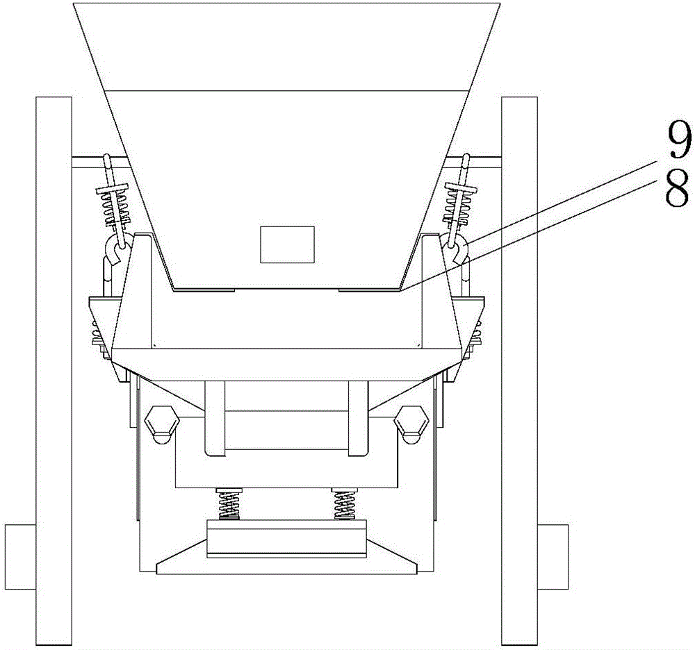
[0025] An electromagnetic vibrating feeder, such as figure 1 , figure 2 As shown, it includes an electromagnetic vibrator 1, an electromagnetic vibrator base 2, a feeder support 3, a feed hopper 4, a sieve plate 5, a shock absorber 6 and a feeding trough 7; the electromagnetic vibrator 1 is fixed on the electromagnetic vibrator through a spring connection. On the vibrator base 2, the electromagnetic vibrator 1 is connected with the feed trough 7 by bolts; the inside of the feed trough 7 is equipped with a slope support 8, and the outer wall is welded with hanging ears 9; the feed hopper 4 is placed on the slope support 8 and connected to the slope The bracket 8 is wedged together, and the bottom of the feeding hopper 4 is fixedly equipped with a sieve plate 5; the shock absorber 6 has hooks at both ends, and the hooks at both ends are respectively connected to the cross bar of the feeder bracket 3 and the hanging ear 9 of the feeding trough.

[0026] Turn on the electromagne...

Embodiment 2

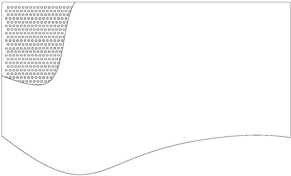
[0031] In order to further enhance the passing rate of the material through the sieve plate, the mesh of the sieve plate is processed into a regular hexagon or a circle.

Embodiment 3

[0033] In order to further strengthen the screening efficiency, the aftershock of the electromagnetic vibration feeder is utilized, and at the same time, the friction force between the feed hopper and the feed chute is reduced. The inventor also fixes rubber flexible gaskets on the inclined plane support 8 of the feed trough, and the gaskets The thickness is 1mm-3mm.


PUM


Abstract

The invention relates to the field of mechanical vibration and particularly relates to an electromagnetic vibrating feeder. The electromagnetic vibrating feeder comprises an electromagnetic vibrator (1), an electromagnetic vibrator base (2), a feeder bracket (3), a feeding hopper (4), a sieve plate (5), a vibration adsorber (6) and a feeding groove (7). By improving the electromagnetic vibrating feeder and additionally mounting the sieve plate (5) and the feeding hopper (4), purposes of separating materials and performing vibrating feeding are achieved. By improving a half-wave rectifying circuit of the electromagnetic vibrator and reversely connecting a diode, purposes of braking quickly and protecting a coil can be achieved.

Description

[0001] 【Technical field】 [0002] The invention relates to the field of mechanical vibration, in particular to an electromagnetic vibration feeder. [0003] 【Background technique】 [0004] Electromagnetic vibrating feeder is a kind of equipment for automatic flow operation, which is used to uniformly or quantitatively supply materials from storage bins or other storage equipment to receiving equipment. The electromagnetic vibrating feeder has a simple structure and is easy to operate. , does not need lubrication, low power consumption, and can adjust the feeding amount, so it has been widely used. The electromagnetic vibrating feeder uses the half-wave rectified unidirectional pulsating current to flow through the coil in the motor of the electromagnetic vibrating feeder. The corresponding pulse electromagnetic force is generated, and the reciprocating vibration is continuously carried out according to the frequency of the alternating current, and the vibration frequency is uni...

Claims


Application Information

Patent Timeline
Patent Type & Authority Applications(China)
IPC IPC(8): B65G27/04B65G27/24B65G47/18B65G69/12
CPCB65G27/04B65G27/24B65G47/18B65G69/12B65G2201/04
Inventor 梁家祥
Owner GUANGXI UNIV
Learn More