
Method for forming aortic stent graft

A molding method and technology of covered stents, which are applied in stents, devices for human tubular structures, medical science, etc., can solve problems such as long process time, poor geometrical compliance of blood vessels, and stress tearing at the distal end of stents.

Inactive Publication Date: 2017-03-15
TSINGHUA UNIV +1
View PDF7 Cites 18 Cited by
  • Summary
  • Abstract
  • Description
  • Claims
  • Application Information

AI Technical Summary

Problems solved by technology

The main problem with the existing covered stents is that they are all designed as standard equipment, which leads to poor geometric compliance to the course of blood vessels and cannot effectively match the characteristics of individual lesions (such as tortuous aorta, large lesion diameter, etc. ), resulting in endoleakage in some treated individuals due to poor apposition and excessive stress at the distal end of the stent that tears the intima and leads to treatment failure; although the production of individualized stents is clinically feasible, the existing process takes a long time and cannot Timely use in the treatment of patients and cannot be widely carried out
3D printing technology has successfully printed models for aortic diseases, and obtained more comprehensive and intuitive anatomical information, but there are few studies on the production of stent grafts based on this technology, and it is difficult to avoid toxic substances in the production process

Method used


Image

  • Method for forming aortic stent graft
  • Method for forming aortic stent graft
  • Method for forming aortic stent graft

Examples


Embodiment Construction

[0039] The experimental methods used in the following examples are conventional methods unless otherwise specified.

[0040] The materials and reagents used in the following examples can be obtained from commercial sources unless otherwise specified.

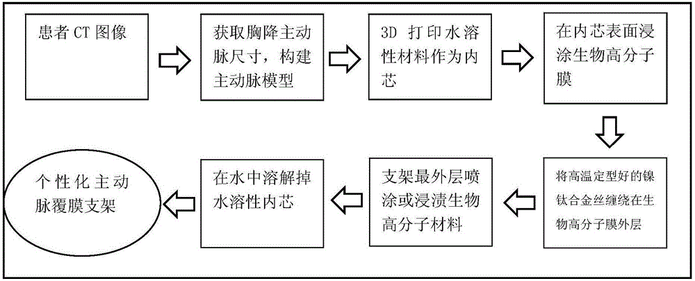
[0041] according to figure 1 The flow chart shown produces the descending thoracic aortic stent graft, and the steps are as follows:

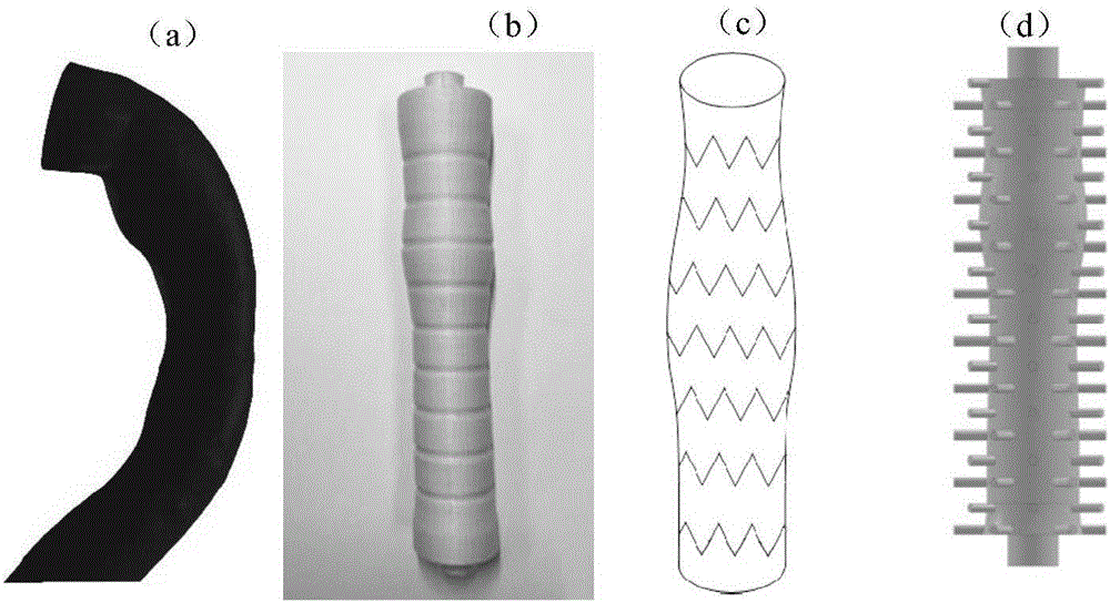
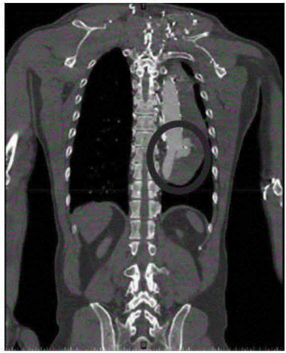
[0042] (1) Obtain a descending thoracic aorta image with a length of about 200 mm according to the patient's CT scan, and use Mimics 10.1 software to extract a three-dimensional model of the vessel, as shown in figure 2 As shown in (a), along the axial direction of the blood vessel, the characteristic diameter of the blood vessel is extracted every 10mm.

[0043] (2) According to the extracted blood vessel data, use CAD software to reconstruct the blood vessel model, and 3D print out the water-soluble blood vessel inner core, such as figure 2 As shown in (b), the water-soluble material is po...


PUM


Abstract

The invention discloses a method for forming an aortic stent graft. The method comprises the following steps: acquiring an image of aorta, and extracting a three-dimensional (3D) model of the aorta according to the image; extracting diameter characteristics of the aorta in the axial direction of the aorta of the 3D model; reconstructing an aortic vascular model according to the extracted diameter characteristics; 3D-printing a water-soluble vascular inner core according to the aortic vascular model; dip-coating a polymer film on a surface of the water-soluble vascular inner core; spirally weaving a metal mesh outside the treated water-soluble vascular inner core as a metal stent; bonding the polymer film and the metal stent, and then removing the water-soluble vascular inner core to obtain the aortic stent graft. The method provided by the invention can efficiently and accurately manufacture a vascular stent graft according to the actual size of a thoracic descending aorta of a patient based on a 3D printing technology, can effectively solve a detect that an existing equal-diameter vascular stent does not match a true vascular size of the patient, provides an effective medical means for treatment of acute vascular aneurysm, and has important clinical value.

Description

technical field [0001] The invention relates to a molding method of an aortic covered stent, belonging to the field of biomedical materials. Background technique [0002] Descending thoracic aortic aneurysm disease, including aortic dissection and aortic aneurysm, has a high natural mortality rate. At present, endovascular exclusion has been widely promoted and become an effective method for the treatment of descending aortic dilatation. The key to endovascular isolation therapy is the effectiveness of the stent graft system. The main problem with the existing covered stents is that they are all designed as standard equipment, which leads to poor geometric compliance to the course of blood vessels and cannot effectively match the characteristics of individual lesions (such as tortuous aorta, large lesion diameter, etc. ), resulting in endoleakage in some treated individuals due to poor apposition and excessive stress at the distal end of the stent that tears the intima and...

Claims


Application Information

Patent Timeline
IPC IPC(8): A61F2/07B33Y10/00
CPCA61F2/07A61F2/0077A61F2230/0002A61F2240/002B33Y10/00
Inventor 张磊陈鑫林峰李雷唐锋刘思博张婷
Owner TSINGHUA UNIV
Learn More