
Detection-diagnosis device and method for vibration fault of aeroengine

A technology for aero-engines and faults, applied in measuring devices, measuring ultrasonic/sonic/infrasonic waves, instruments, etc., can solve the problems that the engine cannot be installed, affects the results of vibration analysis and diagnosis, and cannot guide the on-site vibration test and vibration elimination process, etc., to achieve The effect of improving the qualification rate and vibration elimination success rate and improving the level of vibration analysis

Inactive Publication Date: 2017-03-08
SHENYANG LIMING AERO-ENGINE GROUP CORPORATION
View PDF6 Cites 9 Cited by
  • Summary
  • Abstract
  • Description
  • Claims
  • Application Information

AI Technical Summary

Problems solved by technology

[0005] 1) The vibration sensor is installed on the casing, and the vibration signals picked up at different positions are affected by the transmission path differently, which affects the vibration analysis and diagnosis results;
[0006] 2) Axial vibration is important information in the process of engine vibration fault analysis and diagnosis, and plays an important role in judging misalignment faults. The finalized engine cannot be installed
Simultaneous monitoring and analysis of three-way vibration at the same measuring point, there is no evaluation standard for aero-engine vibration fault diagnosis, and it cannot guide the on-site vibration test and vibration removal process

Method used


Image

  • Detection-diagnosis device and method for vibration fault of aeroengine
  • Detection-diagnosis device and method for vibration fault of aeroengine
  • Detection-diagnosis device and method for vibration fault of aeroengine

Examples


Embodiment Construction

[0031] The specific implementation manners of the present invention will be described in detail below in conjunction with the accompanying drawings.

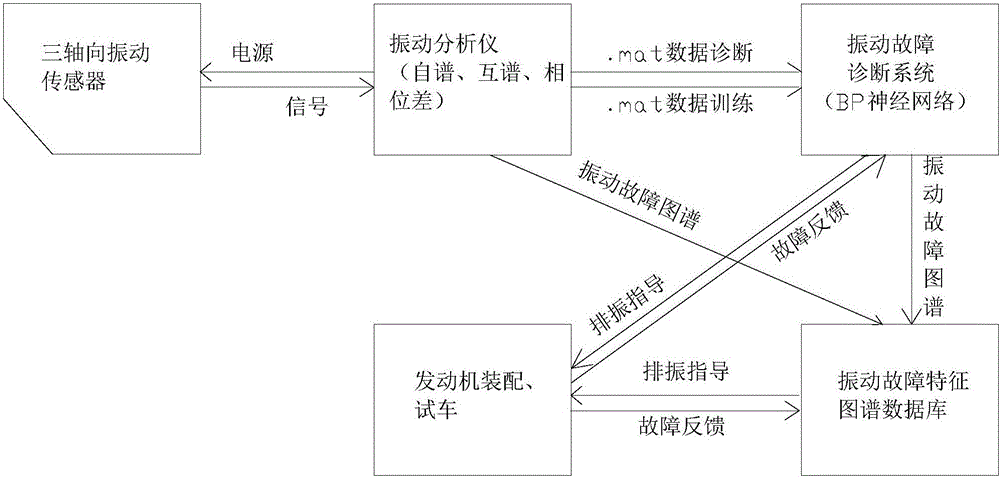
[0032] A device for detecting and diagnosing vibration faults of aero-engines, such as figure 1 shown, including:

[0033] Three-axis vibration sensor: installed on the case of a faulty aero-engine with vibration exceeding the standard, to measure horizontal, vertical and axial vibrations; in this embodiment, the B&K4321V three-axis vibration sensor is selected, which has good stability and high reliability. Internal integrated ICP circuit, single screw installation, suitable for production site use. B&K 4321V three-axis vibration sensor X, Y, Z respectively measure the vibration acceleration signals of the horizontal, vertical and axial directions of the aero-engine.

[0034] Vibration analyzer: supplies power to the three-axis vibration sensor and detects vibration fault signals; obtains the vibration fault characteristic ma...


PUM


Abstract

The invention provides a detection-diagnosis device and method for a vibration fault of an aeroengine. The device comprises a three-axial-direction vibration sensor, a vibration analyzer and an industrial control computer; the three-axial-direction vibration sensor is mounted on a casing of the aeroengine with a vibration standard exceeding fault, and measures vibration in horizontal, vertical and axial directions of the aeroengine with the fault; the vibration analyzer supplies power to the three-axial-direction vibration sensor, detects a vibration fault signal, obtains a vibration fault characteristic atlas according to the detected vibration fault signal, and outputs the vibration fault characteristic atlas and the vibration signal to the industrial control computer; and the industrial control computer diagnoses the vibration fault of the aeroengine with the fault according to the vibration fault signal, and obtains the type of the vibration fault of the aeroengine by diagnosis. The device and method are applied to whole-machine vibration test analysis and vibration fault diagnosis and elimination fields during rack test of the aeroengine, to vibration fault analysis and diagnosis in outfield engine ground test and airplane flight process, and to vibration fault analysis and diagnosis when a core unit is tested.

Description

technical field [0001] The invention relates to the technical field of aero-engines, in particular to a device and method for detecting and diagnosing vibration faults of aero-engines. Background technique [0002] More than 90% of aero-engine structural strength failures are caused by or related to vibration. The reasons for these phenomena are mainly due to the lack of deep understanding of the vibration of the whole machine during design and use, the lack of systematic design theory and methods, backward test methods and analysis methods, and imperfect evaluation standards. [0003] At present, the vibration analysis and diagnosis technology of aero-engine mainly adopts single-axis vibration sensor to measure the vibration in the horizontal or vertical direction, and uses FFT spectrum analysis or speed tracking technology to analyze and diagnose the vibration fault signal. [0004] The disadvantages of the prior art are: [0005] 1) The vibration sensor is installed on ...

Claims


Application Information

Patent Timeline
IPC IPC(8): G01H17/00
CPCG01H17/00
Inventor 王海霞谭亮赵雪原荆涛冯鑫
Owner SHENYANG LIMING AERO-ENGINE GROUP CORPORATION
Learn More