
Concentrating solar photo-thermal and photoelectric mixed collector

A photothermal photoelectric and solar energy technology, applied in solar thermal power generation, solar collectors, photovoltaic thermoelectric hybrid power generation, etc., can solve the problem of limiting the maximum temperature of photothermal units, increasing heat conduction, convection, radiation heat dissipation, and reducing photothermal units. Heating efficiency and other issues, to achieve the effect of improving the heat production efficiency and the grade of heat energy, improving the photoelectric efficiency, and reducing the heat loss of the system

Active Publication Date: 2017-03-08
TONGJI UNIV
View PDF13 Cites 2 Cited by
  • Summary
  • Abstract
  • Description
  • Claims
  • Application Information

AI Technical Summary

Problems solved by technology

[0004] The use of spectral frequency division technology based on nanofluids can effectively increase the heat collection temperature of the photothermal unit in the solar thermal photoelectric hybrid collection system, but the heat conduction, convection, and radiation heat loss between the photothermal unit and the environment continue to increase as the temperature increases. Increase, this heat loss reduces the heating efficiency of the photothermal unit and limits the maximum temperature of the photothermal unit

Method used


Image

  • Concentrating solar photo-thermal and photoelectric mixed collector
  • Concentrating solar photo-thermal and photoelectric mixed collector
  • Concentrating solar photo-thermal and photoelectric mixed collector

Examples


Embodiment 1

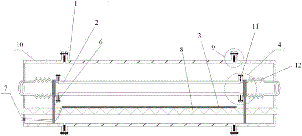
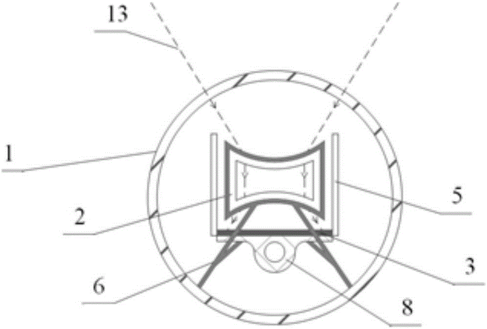
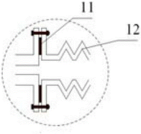
[0027] A concentrating solar photothermal photoelectric hybrid collector, its structure is as follows figure 1 and figure 2 As shown, it includes quartz glass tube 1, quartz heat collector tube 2, photovoltaic cell 3, battery cooling channel 8, thermal expansion offset structure 4, reflector 5, support module 6, wire outlet interface 7, flange sealing structure 9, and metal end cover 10. The high temperature resistant sealing ring 11, the metal bellows 12, the photovoltaic cell 3, the quartz heat collecting tube 2 and the battery cooling channel 8 are sealed in the quartz glass tube 1, and the inside thereof is in a vacuum state.

[0028] The quartz heat collecting tube 2 is designed as a single-sided or double-sided concave channel. When the inside of the quartz heat collecting tube 2 passes through the liquid, due to the refraction of light, its special structure can make the converged light become parallel light again (below The surface is flat) or divergent light (the lo...


PUM


Abstract

The invention relates to a concentrating solar photo-thermal and photoelectric mixed collector. The collector comprises quartz heat colleting tubes which are internally filled with semitransparent liquids, a photovoltaic cell and a cooling channel thereof. The collector further comprises reflectors arranged on two sides of the quartz heat collecting tubes, quartz glass tubes externally surrounding the quartz heat collecting tubes, the photovoltaic cell and the battery cooling channel, metal end covers at two ends of the quartz glass tubes and thermal expansion counteracting structures. The quartz glass tubes tightly seal the heat collecting tubes in a vacuum environment, so that the heat loss of the heat collecting tubes is reduced; the quartz heat collecting tubes are designed as single-sided or double-sided concave channels, so that the incident rays at the photovoltaic cell are more uniform, and therefore, the photoelectric efficiency is improved and the pressure bearing capacities of the quartz heat collecting tubes are improved; and the thermal expansion counteracting structures absorb axial thermal deformation at a high temperature of the heat collecting tubes. Compared with the prior art, the solar utilization ratio of the photo-thermal and photoelectric mixed collector is effectively improved, the problems of thermal expansion and pressure resistance of the heat collecting tubes are solved, and the stability of the mixed collector is improved.

Description

technical field [0001] The invention relates to the technical field of combined solar heat and power, in particular to a concentrating solar photothermal photoelectric hybrid collector. Background technique [0002] Solar energy is an important renewable energy with the characteristics of large amount, wide distribution, cleanness and safety. Efficient use of solar energy has become one of the effective ways to solve the global energy shortage and environmental pollution problems. [0003] Traditional solar-thermal-photoelectric hybrid harvesting systems usually collect heat energy by arranging cooling channels on the back of photovoltaic cells. However, due to the limitation of the operating temperature of photovoltaic cells, such a system cannot obtain higher temperature thermal energy, which limits its expansion in the industrial field. Recently, the solar spectral frequency division technology based on nanofluids has released the thermal coupling between photovoltaic c...

Claims


Application Information

Patent Timeline
IPC IPC(8): F24J2/00H02S40/44H02S40/42
CPCF24S21/00F24S2020/17H02S40/425H02S40/44Y02E10/40Y02E10/50Y02E10/60
Inventor 安巍吴锦瑞朱彤秦瑶
Owner TONGJI UNIV
Learn More