Eureka AIR delivers breakthrough ideas for toughest innovation challenges, trusted by R&D personnel around the world.

Mixed ventilation cooling system and method for permanent magnet traction motor

A traction motor, ventilation and cooling technology, applied in the direction of cooling/ventilation devices, electromechanical devices, electrical components, etc., can solve the problems of low indirect cooling efficiency of permanent magnets, affect the heat transfer of permanent magnets, and it is difficult to ensure the heat dissipation capacity, etc., to achieve Balance temperature rise, enhance heat dissipation, and ensure uniformity

Active Publication Date: 2017-02-22
SHENYANG POLYTECHNIC UNIV
View PDF4 Cites 4 Cited by
  • Summary
  • Abstract
  • Description
  • Claims
  • Application Information

AI Technical Summary

Problems solved by technology

In addition, due to the needs of the installation process and production process, there is a large gap between the permanent magnet and the installation slot opened in the rotor core, which affects the heat transfer of the permanent magnet.
The indirect cooling efficiency of the traditional permanent magnet motor axial ventilation system for the permanent magnet is low, and it is difficult to guarantee its heat dissipation capacity
However, in the mixed ventilation structure of asynchronous motors in the past, the radial air path and the axial air path are cross-linked, and the wind resistance loss of small and medium-sized traction motors is relatively large, which limits the efficiency of the motor.

Method used


Image

  • Mixed ventilation cooling system and method for permanent magnet traction motor
  • Mixed ventilation cooling system and method for permanent magnet traction motor
  • Mixed ventilation cooling system and method for permanent magnet traction motor

Examples


Embodiment Construction

[0030] Below in conjunction with accompanying drawing, the present invention will be further described:

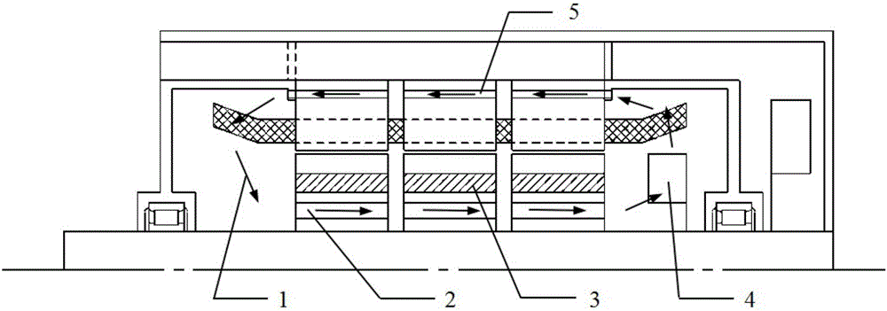
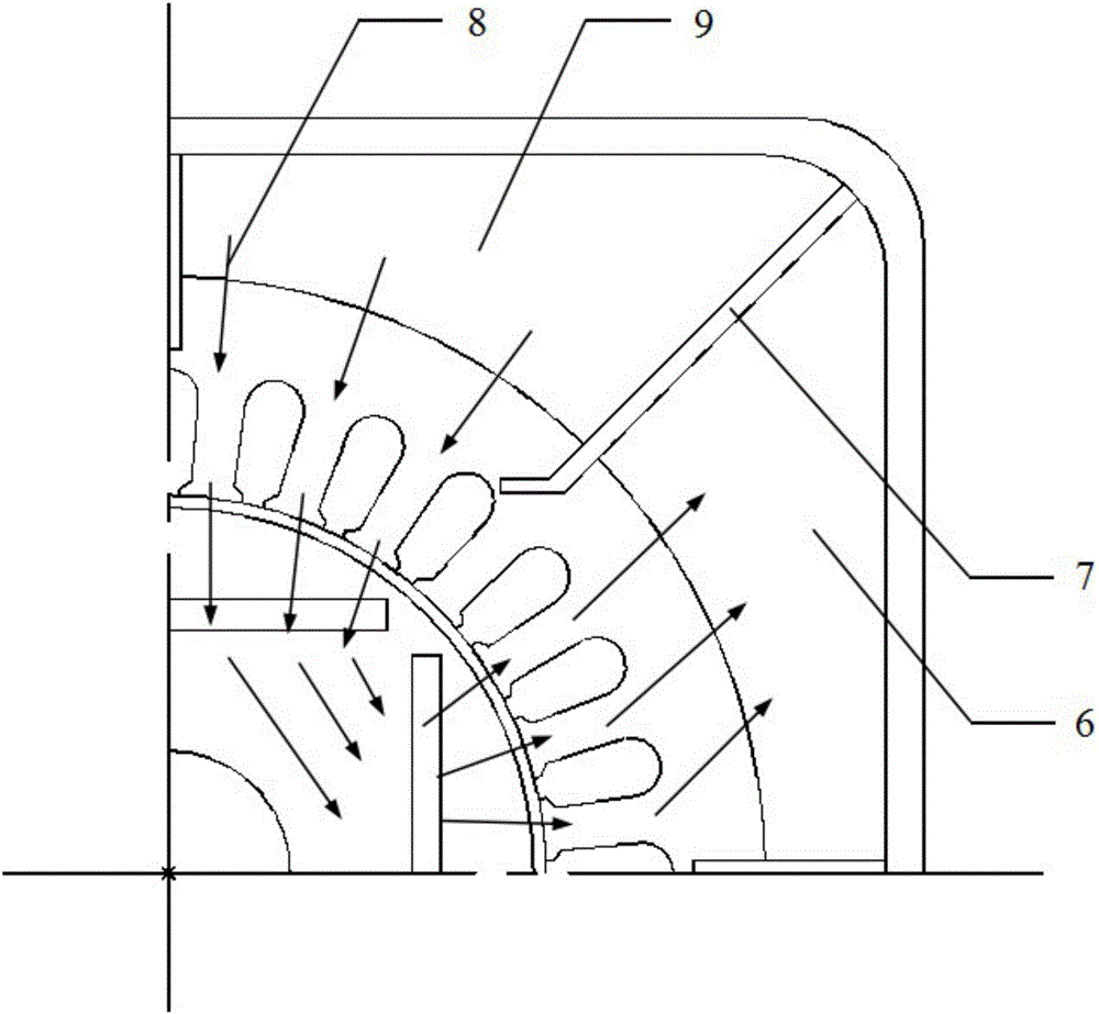
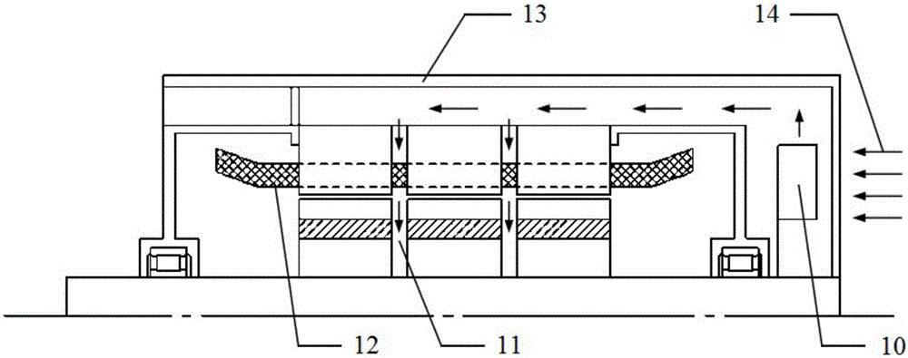
[0031] The present invention proposes a hybrid ventilation and cooling system for permanent magnet traction motors, such as Figure 1~Figure 5 As shown, the bearing 17 of the motor is installed between the end cover 20 and the rotating shaft 21 , the stator coil 12 is wound in the slot of the stator core 19 , and the permanent magnet 3 is built in the rotor core 18 . The cooling system is divided into radial ventilation system and axial ventilation system.

[0032] Axial ventilation system includes rotor core laminations punched out of rotor axial ventilation hole configuration and stacked to form rotor axial ventilation hole 2, stator core laminations punched out of stator axial ventilation hole configuration and laminated to form stator shaft To the ventilation hole 5, and the centrifugal fan 4 of the axial air path; the centrifugal fan 4 of the axial air path is instal...


PUM


Abstract

The invention relates to a mixed ventilation cooling system and method for a permanent magnet traction motor. The cooling system consists of a radial ventilation cooling system and an axial ventilation cooling system which are independently driven to work, the radial ventilation cooling system is used for directly blowing and cooling a rotor and a permanent magnet, and the axial ventilation cooling system is used for cooling an end winding and balancing the temperature rise of the whole motor. According to the system and the method, radial ventilation and axial ventilation are separated in terms of mass transfer, and the wind resistance loss of the ventilation systems is relatively low; seriously heated positions in the motor are cooled by the two sets of ventilation systems respectively, so that high cooling performance is achieved; the radial ventilation cooling system is divided into two parts, namely, an air inlet passage and an air outlet passage, by a separation plate, and the temperature rise of cooling air entering each radial air vent is similar, so that axial balance of the temperature rise of the motor is ensured; circumferential balance of the temperature rise of the motor is ensured by the axial ventilation cooling system. The system and the method have the characteristics of good motor interior cooling effects and good motor temperature rise balance, and are suitable for popularization and application.

Description

technical field [0001] The invention relates to the technical field of motor manufacturing, mainly to a motor cooling system, in particular to a cooling system for a permanent magnet traction motor of small and medium-sized rail transit, public transportation, and electric vehicles, specifically to a cooling system with two sets of axial and radial ventilation paths. A permanent magnet traction motor cooling system and method. Background technique [0002] Permanent magnet motors have the characteristics of high efficiency and high power density, and can maintain high efficiency and power factor under light-load operation conditions. Compared with asynchronous motors as traction motors, they can effectively save energy in the long-term operation of electric vehicles. . Since the electric vehicle motor is controlled by a frequency converter and the operating frequency is often high, there are a large number of space harmonics and time harmonics in the motor rotor and permane...

Claims


Application Information

Patent Timeline
IPC IPC(8): H02K1/32H02K1/20H02K9/02
CPCH02K1/20H02K1/32H02K9/02
Inventor 佟文明朱高嘉韩雪岩吴胜男宁杰唐任远
Owner SHENYANG POLYTECHNIC UNIV
Why Eureka
Eureka Blog
Learn More