Packaging structure of heavy current field effect transistors
A field effect tube and packaging structure technology, applied in the direction of circuits, electrical components, electric solid devices, etc., can solve the problems of affecting work, large volume, softening of solder joints, etc., and achieve the minimum overall structure, compact overall structure, and reliable connection Effect
- Summary
- Abstract
- Description
- Claims
- Application Information
AI Technical Summary
Problems solved by technology
Method used
Image
Examples
Embodiment Construction
[0036] Embodiments of the present invention will be described in detail below in conjunction with the accompanying drawings.
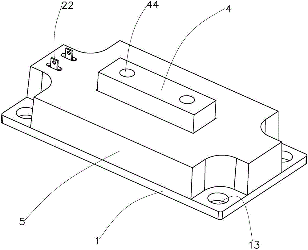
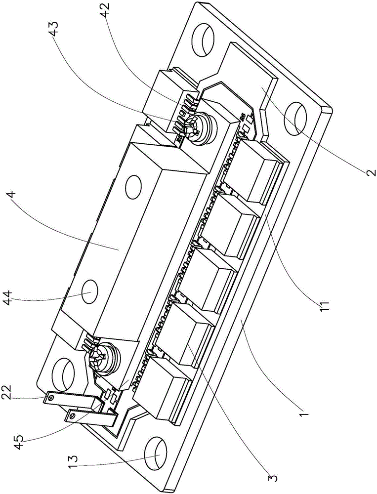
[0037] Such as figure 2 , image 3 with Figure 4 As shown, the packaging structure of a large current field effect transistor of the present invention includes a conductive base 1, an electrode connection base 4, a field effect tube 3 and a circuit board 2, and the electrode connection base 4 is fixedly insulated and connected to the conductive base 1 , and the circuit board 2 is placed between the electrode connection seat 4 and the conductive base 1, the bottom of the electrode connection seat 4 is electrically connected to the front of the circuit board 2, and the back of the circuit board 2 is connected to the conductive base 1, plural The G / S pole pins 31 of each of the field effect transistors 3 are all facing the electrode connection seat 4 and welded to the side of the circuit board 2, and the D pole pins 32 of each of the field effect tran...
PUM
 Abstract
Description
Claims
Application Information
 - R&D
- Intellectual Property
- Life Sciences
- Materials
- Tech Scout
- Unparalleled Data Quality
- Higher Quality Content
- 60% Fewer Hallucinations
Browse by: Latest US Patents, China's latest patents, Technical Efficacy Thesaurus, Application Domain, Technology Topic, Popular Technical Reports.
© 2025 PatSnap. All rights reserved.Legal|Privacy policy|Modern Slavery Act Transparency Statement|Sitemap|About US| Contact US: help@patsnap.com


