
Electric-heat-aging junction temperature calculation model establishing method of IGBT module

A technology for establishing a method and a calculation model, which is applied in the field of establishment of an electric-thermal-aging junction temperature calculation model, and can solve problems such as inaccurate prediction results of the junction temperature of the electric-thermal coupling model, damage, etc.

Active Publication Date: 2017-02-22
HEBEI UNIV OF TECH
View PDF9 Cites 87 Cited by
  • Summary
  • Abstract
  • Description
  • Claims
  • Application Information

AI Technical Summary

Problems solved by technology

The maximum junction temperature of the IGBT module is usually greater than its average junction temperature. Under severe working conditions such as high frequency, high power, and high temperature, the IGBT module is likely to be damaged due to the maximum junction temperature exceeding the critical temperature. The transient junction temperature prediction of the module can provide a technical reference for improving the reliability of the power electronic system, so it is widely used. However, the current IGBT junction temperature simulation analysis method fails to consider the influence of module aging on the electrothermal parameters, which makes the electrothermal Inaccurate Junction Temperature Predictions from Coupled Models

Method used


Image

  • Electric-heat-aging junction temperature calculation model establishing method of IGBT module
  • Electric-heat-aging junction temperature calculation model establishing method of IGBT module
  • Electric-heat-aging junction temperature calculation model establishing method of IGBT module

Examples


Embodiment Construction

[0062] Embodiments of the present invention are described in further detail below in conjunction with the accompanying drawings:

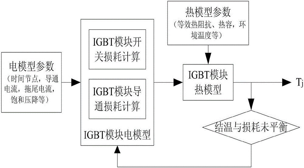
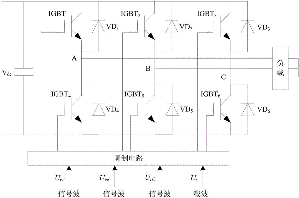
[0063] figure 1 A block diagram of the electric-thermal coupling model of the IGBT module is given. Below to figure 2 The three-phase six-bridge inverter circuit shown is taken as an example to introduce the establishment process of the electric-thermal-aging junction temperature calculation model in detail. The IGBT module is MMG75S120B from Macmic Company. The module consists of two identical parts, each part consists of an IGBT and a diode, and the rated conditions of the IGBT and the diode are 1200V / 75A. The chip is soldered to the DCB substrate through lead-free solder paste, and the upper part of the chip is connected to the DCB substrate through aluminum bonding wires.

[0064] The electric-thermal-aging junction temperature calculation model establishment method of IGBT module of the present invention comprises the following steps:

[...


PUM


Abstract

The invention relates to an electric-heat-aging junction temperature calculation model establishing method of an IGBT module. The method is technologically characterized by comprising the following steps of testing electric heating parameters of the IGBT module in different aging degrees, acquiring a three-dimensional relation curved surface and establishing an electric heating data sheet in different aging degrees; establishing an electric model of the IGBT module and a thermal network model of the IGBT module, inputting a power loss which is calculated through the electric model of the IGBT module into the thermal network model of the IGBT module in a current source manner, performing real-time feedback of the junction temperature which is calculated by the thermal network model to the electric model, and finishing establishment of an electric-heat coupling model of the IGBT module; performing aging state evaluation on the IGBT module; and performing junction temperature calculation on the IGBT module. According to the electric-heat-aging junction temperature calculation model establishing method, the corresponding electric heating parameters for different aging processes are acquired and furthermore the electric heating parameters are input into the electric-heat coupling model for performing junction temperature calculation, namely the parameter of the electric-heat coupling model is dynamically changed in real time according to the aging degree of the model, thereby realizing a junction temperature prediction function for the module aging degree.

Description

technical field [0001] The invention belongs to the technical field of power electronic devices, in particular to a method for establishing an electric-thermal-aging junction temperature calculation model of an IGBT module. Background technique [0002] IGBT power modules are widely used in various fields such as rail transit, smart grid, electric vehicles and new energy. The junction temperature of the IGBT power module is a very important characteristic parameter for the reliable and stable operation of the power converter. The fluctuation of the junction temperature will directly affect the working performance and reliability of the power converter. The long-term junction temperature fluctuation It will cause aging and even failure of the device. The failure of the IGBT is mainly related to the failure of the package. Due to the different thermal expansion coefficients of the materials of the various layers of the IGBT module, the alternating thermal stress caused by the...

Claims


Application Information

Patent Timeline
IPC IPC(8): G01R31/26
CPCG01R31/2601G01R31/2642
Inventor 李玲玲许亚惠李志刚齐福东刘伯颖周亚同
Owner HEBEI UNIV OF TECH
Learn More