


Quick Research
Generate reliable direction feasibility study reports for your R&D in just a few steps.

Technical Q&A
Discover and master advanced knowledge NOW. Basics, ideas, possibilities, all at once.

Find Solutions
As an expert in R&D theories, this can generate solutions to your technical problems instantly.

Evaluate Feasibility
Analyze your overall solution with one click, know your potential R&D risks in advance.

Monitor Landscape
Get weekly tech updates, stay abreast of the latest tech innovations and key insights.
Internal combustion engine tail gas utilization heat energy power system based on multistage pressurization condensation
A power system and internal combustion engine technology, applied in the direction of machines/engines, generators/motors, steam/steam condensers, etc., can solve problems such as large waste of heat energy, small external waste heat absorption rate, and unstable gasification temperature of working fluid. Achieve stable gasification temperature and working medium flow rate, improve gasification efficiency and condensation efficiency, and avoid unstable turbine speed
- Summary
- Abstract
- Description
- Claims
- Application Information
AI Technical Summary
Problems solved by technology
Method used
Image

Examples
Embodiment 1
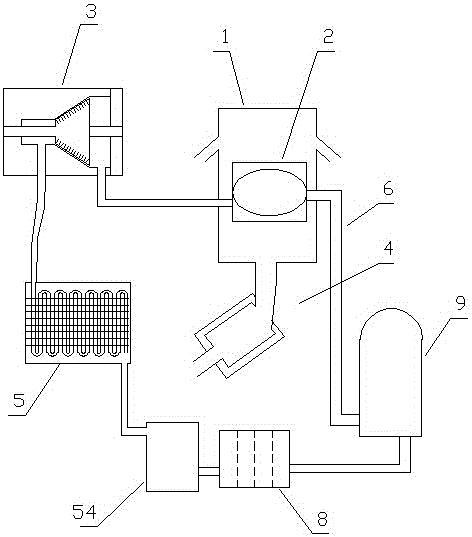
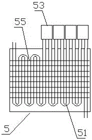
[0079] Embodiment one (such as figure 1 Shown): a power system based on multi-stage supercharging and condensation for utilization of heat energy from internal combustion engine exhaust, including a heat collector 1, a gasification device 2, a turbine 3, an internal combustion engine exhaust pipe 4, a condensation device 5, a circulation pipeline 6, and a circulating working fluid 7 and the one-way hydraulic pump 9, the gasification device 2, the turbine 3, the condensing device 5 and the one-way hydraulic pump 9 realize circulation communication through the circulation pipeline 6 in sequence, the circulation pipeline 6 contains the circulating working medium 7, and the heat collection device 1 is installed on The outside of the gasification device 2 is used for gasification and heating of the working fluid in the gasification device 2;
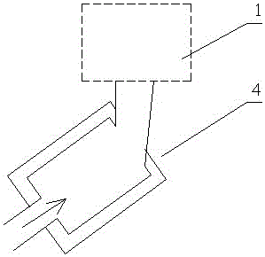
[0080] (Such as figure 2 As shown) the exhaust pipe 4 of the internal combustion engine is connected to the heat collector 1;
[0081] (S...
Embodiment 2
[0090] Embodiment two (such as Figure 6 Shown): The difference from Embodiment 1 is that the heat collecting device 1 includes an upper cover 11 and a lower cover 12, a heating port 13 is provided in the middle of the lower cover 12, and the upper cover 11 and the lower cover 12 are respectively located on the upper and lower sides. Between 11 and the lower cover 12 is a heat collecting chamber 14, two layers of upper cover protruding rings 111 are distributed on the lower part of the upper cover 11 of the heat collecting device 1, and two layers of lower cover protruding rings 121 are distributed on the upper part of the lower cover 12 of the heat collecting device 1, The protruding ring 111 of the upper cover and the protruding ring 121 of the lower cover are staggered.
[0091] By carrying out experiments on the internal combustion engine tail gas utilization heat energy power system based on multi-stage pressurized condensation in the above-mentioned embodiment two, exha...
Embodiment 3
[0092] Embodiment three (such as Figure 7 Shown): The difference from Embodiment 1 is that the lower part of the upper cover 11 of the heat collecting device 1 is provided with a three-layer upper cover protruding ring 111, and the upper part of the lower cover 12 of the heat collecting device 1 is distributed with a three-layer lower cover protruding ring 121 , the upper cover protruding ring 111 and the lower cover protruding ring 121 are staggered.
[0093] By carrying out experiments on the internal combustion engine tail gas utilization heat energy power system based on multi-stage pressurized condensation in the above-mentioned embodiment three, exhaust gas at different temperatures is discharged into the heat collector 1, the exhaust gas displacement is 1.5L / s, and the working medium flow rate in the circulation pipe Adjusted according to the operation stability of the internal combustion engine exhaust gas utilization heat energy power system based on multi-stage pre...
PUM
 Abstract
Description
Claims
Application Information
 - R&D Engineer
- R&D Manager
- IP Professional
- Industry Leading Data Capabilities
- Powerful AI technology
- Patent DNA Extraction
Browse by: Latest US Patents, China's latest patents, Technical Efficacy Thesaurus, Application Domain, Technology Topic, Popular Technical Reports.
© 2024 PatSnap. All rights reserved.Legal|Privacy policy|Modern Slavery Act Transparency Statement|Sitemap|About US| Contact US: help@patsnap.com