
A monitoring system for longitudinal tearing and deviation of steel cord belt conveyor

A technology of longitudinal tearing and monitoring system, which is applied in the direction of conveyor objects, transportation and packaging, conveyor control devices, etc., can solve the problem of not being able to detect tape tearing in time, and achieve shortened downtime, practical technology, and simple installation and maintenance Effect

Inactive Publication Date: 2018-07-27
ANHUI UNIV OF SCI & TECH
View PDF3 Cites 0 Cited by
  • Summary
  • Abstract
  • Description
  • Claims
  • Application Information

AI Technical Summary

Problems solved by technology

[0006] The purpose of the present invention is to solve the defect that the tape tear cannot be found in time in the prior art, and to provide a longitudinal tear and deviation monitoring system of the steel cord tape machine to solve the above problems

Method used


Image

  • A monitoring system for longitudinal tearing and deviation of steel cord belt conveyor
  • A monitoring system for longitudinal tearing and deviation of steel cord belt conveyor
  • A monitoring system for longitudinal tearing and deviation of steel cord belt conveyor

Examples


Embodiment 1

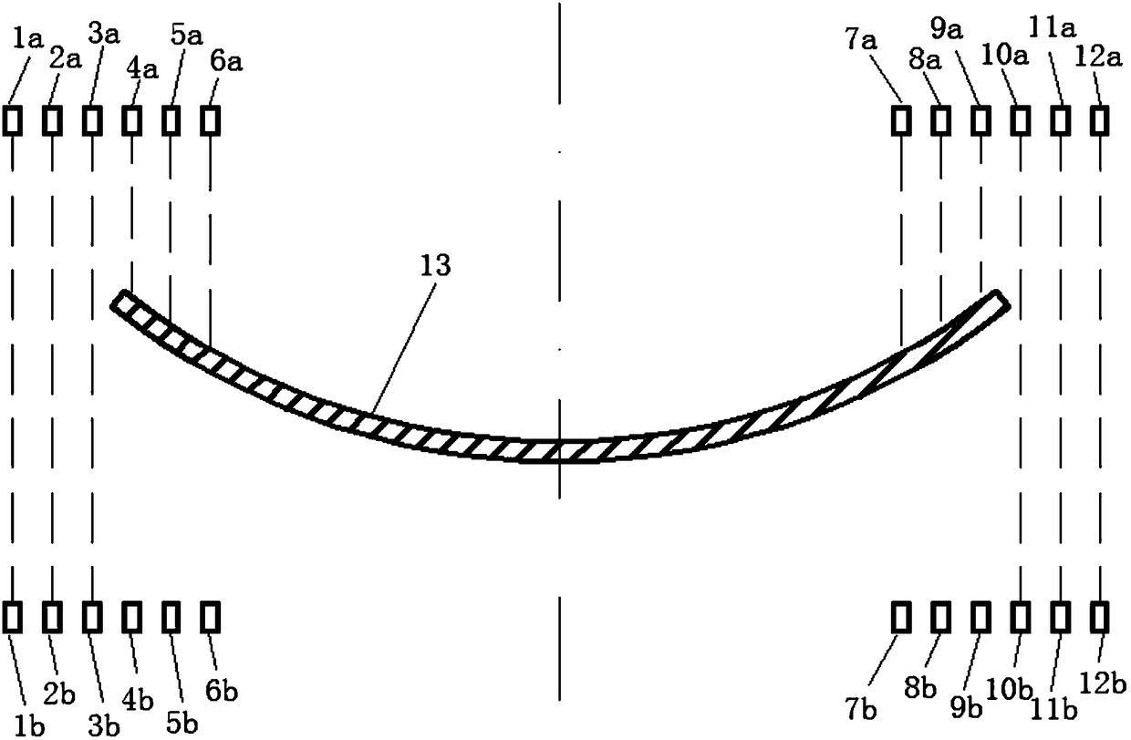
[0029] The number of through-beam laser monitoring devices can be flexibly set according to the width of the tape machine. This embodiment takes 12 groups as an example to describe this scheme in detail:

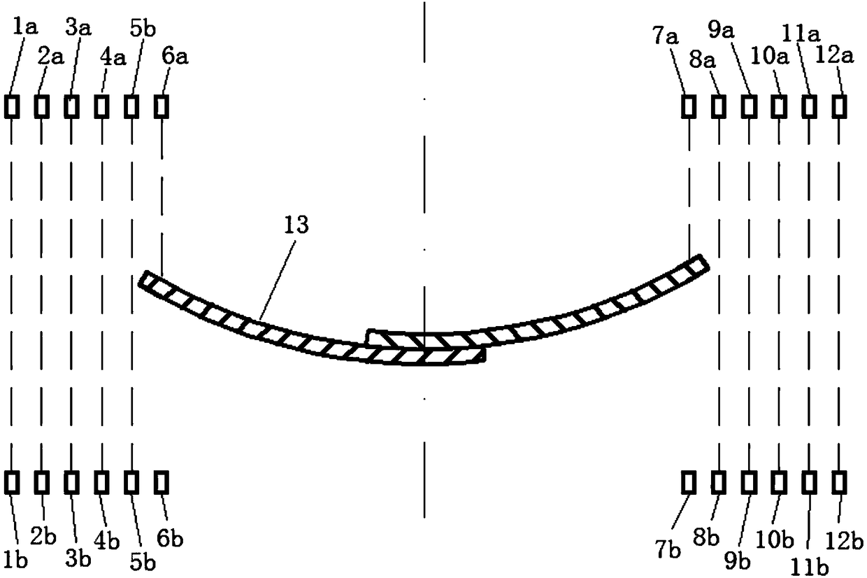
[0030] Such as figure 1 The 12 groups of through-beam laser monitoring devices are the through-beam laser monitoring devices A1 to L12 arranged sequentially from the upper tape 13 from left to right along the width direction of the upper tape 13 . Among them, the laser emitters are arranged horizontally along the tape and symmetrically with the center line of the tape machine above the tape machine, respectively marked as laser emitter A1a ~ laser emitter L12a, and the corresponding laser receivers are arranged directly below it, located on the upper tape 13 Between them and the lower tape, they are marked as laser receiver A1b ~ laser receiver L12b respectively.

[0031]Wherein the through-beam laser monitoring device A1 to the through-beam laser monitoring device F6 and t...


PUM


Abstract

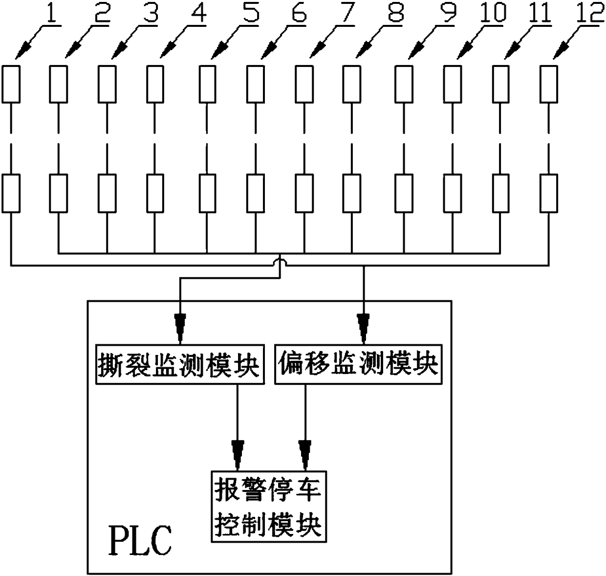
The invention provides a longitudinal tearing and deflecting monitoring system for a steel wire core rubber belt machine. The longitudinal tearing and deflecting monitoring system comprises a PLC (Programmable Logic Controller) and multiple groups of opposite-type laser monitoring devices; laser emitters of the opposite-type laser monitoring devices are fixed above the rubber belt machine along the width direction of the rubber belt machine in a mode of being symmetrical about the central axis of the rubber belt machine; laser receivers are fixed right below the rubber belt machine in a mode of being symmetrical to the laser emitters and are located between an upper rubber belt and a lower rubber belt; the PLC comprises a deflection monitoring module, a tearing monitoring module and an alarming and halting module; at least two groups of opposite-type laser monitoring devices on the outermost side of the two sides of the opposite-type laser monitoring devices communicate with the deflection monitoring module, and the other opposite-type laser monitoring devices communicate with the tearing monitoring module; and the deflection monitoring module and the tearing monitoring module separately communicate with the alarming and halting module. According to match pairing of the plurality of opposite-type laser monitoring devices, belt width change is monitored in real time as a criterion, and timely alarming and halting for a longitudinal tearing accident of the rubber belt machine are finished by utilizing the PLC.

Description

technical field [0001] The invention relates to a supporting device for an underground belt conveyor in a coal mine, in particular to a monitoring system for longitudinal tearing and deviation of a steel cord belt conveyor. Background technique [0002] Compared with other types of tapes, steel cord tape can withstand stronger tension and has a longer service life. It is the most widely used in the belt selection of tape machines, but its price is high and its resistance to longitudinal tearing is poor. Once longitudinal tearing occurs The loss caused by cracking is relatively large, and the normal production time is affected for a long time. [0003] Coal mine underground belt conveyor is the main transportation equipment of the coal mine system. It has a long transportation distance and many reloading points. Because the coal produced by coal mining and tunneling face is often mixed with large pieces of gangue, anchor rods, road logs, etc. Large pieces of hard debris are ...

Claims


Application Information

Patent Timeline
Patent Type & Authority Patents(China)
IPC IPC(8): B65G43/02
CPCB65G43/02
Inventor 尹培坤陈清华姚善化刘续伸
Owner ANHUI UNIV OF SCI & TECH
Learn More