Proximity switch with fault detection function
A proximity switch, fault detection technology, applied in electronic switches, circuit breaker testing, electrical components and other directions, can solve problems such as circuit breakdown, proximity switches have no fault detection function, etc.
- Summary
- Abstract
- Description
- Claims
- Application Information
AI Technical Summary
Problems solved by technology
Method used
Image
Examples
Embodiment 1
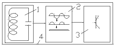
[0015] figure 1 It is a circuit diagram of a proximity switch in the prior art. It can be seen that it is mainly composed of an amplifying oscillation circuit 1, an amplitude detection circuit 2, a switch signal output circuit 3 and a switch housing 4 located outside it.
[0016] figure 2 It is a circuit diagram of the proximity switch of the present invention, in which a fault detection circuit 6 is added. The fault detection circuit includes an amplification oscillation circuit 1, an amplitude detection circuit 2 and a switch signal output circuit 3, and an AND gate logic circuit is arranged between the amplitude detection circuit and the switch signal output circuit.
[0017] Increased fault detection circuit The detection circuit is almost the same as the conventional signal circuit of the proximity switch. The circuit is also divided into three parts: the oscillator, the amplitude processing circuit composed of multi-stage amplifier signals and the switch signal output ...
Embodiment 2
[0020] Embodiment 2: The proximity switch controls the running of the trolley.
[0021] In the process of the proximity switch controlling the action of the field equipment, by approaching the relevant sensing device on the controlled equipment, no direct contact is required, and only after the proximity switch sensing distance is reached, the proximity switch provides a non-contact switching value to control The health of the controlled device.
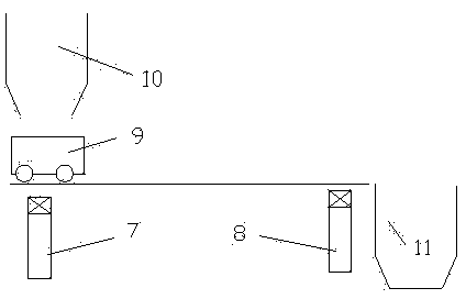
[0022] see image 3 , indicating that the trolley 9 runs along the track. When it reaches the proximity switch 7, it stops for a while to let the bucket 10 unload. After the delay time is up, it runs in the direction of the proximity switch 8. When it reaches the proximity switch 11 unloading, then continue to run to the direction of proximity switch 7, reciprocating cycle.
[0023] Combined with the control circuit below Figure 4 For analysis, 7.1 in the figure represents the contact output of the fault diagnosis circuit of the ...
PUM
 Abstract
Description
Claims
Application Information
 - R&D
- Intellectual Property
- Life Sciences
- Materials
- Tech Scout
- Unparalleled Data Quality
- Higher Quality Content
- 60% Fewer Hallucinations
Browse by: Latest US Patents, China's latest patents, Technical Efficacy Thesaurus, Application Domain, Technology Topic, Popular Technical Reports.
© 2025 PatSnap. All rights reserved.Legal|Privacy policy|Modern Slavery Act Transparency Statement|Sitemap|About US| Contact US: help@patsnap.com


