
Drip chamber and catheter assembling mechanism

An assembly mechanism and catheter technology, applied in the field of medical devices, can solve problems such as reduced work efficiency, energy waste, and reduced assembly success rate

Pending Publication Date: 2017-02-22
梁启明
View PDF1 Cites 2 Cited by
  • Summary
  • Abstract
  • Description
  • Claims
  • Application Information

AI Technical Summary

Problems solved by technology

[0004] The infusion device dripping bottle component assembly machine disclosed in the application number 201220140593.8 includes a frame, a transmission chain is arranged on the frame, and several positioning blocks with positioning grooves are fixedly connected to the transmission chain, and the entrance of the transmission chain A short infusion tube feeding device that can deliver the short infusion tube to the positioning block is fixed at the end, and a drop bottle delivery device for delivering the drop bottle and a two-way connection tube for delivering the two-way connection are fixed on one side of the transmission chain. The two-way connecting pipe assembly device that connects one end of the connecting pipe to the drop bottle is provided on the frame with a short infusion tube assembly device that can connect the other end of the two-way connecting pipe to the short infusion pipe. However, during the assembly process, the dripping funnel is directly assembled with the conduit, resulting in a lower assembly success rate, resulting in a lower work efficiency and a waste of energy

Method used


Image

  • Drip chamber and catheter assembling mechanism
  • Drip chamber and catheter assembling mechanism
  • Drip chamber and catheter assembling mechanism

Examples


Embodiment Construction

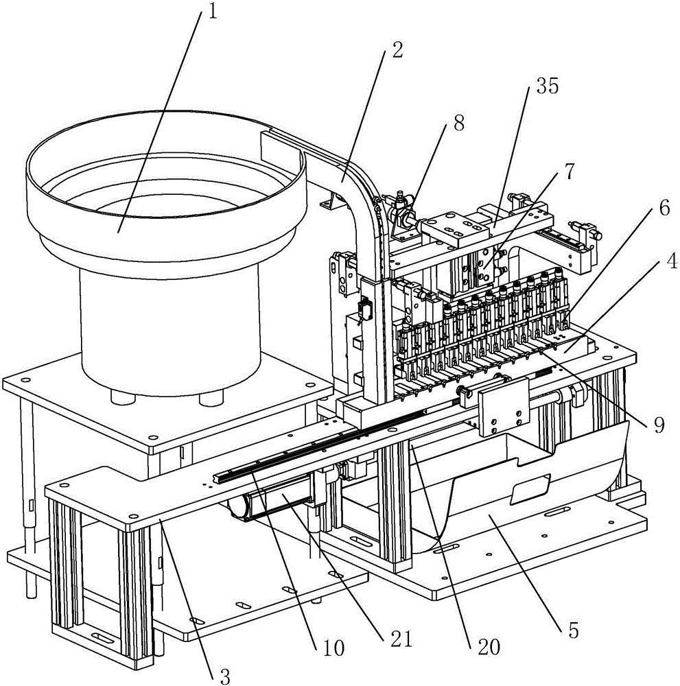
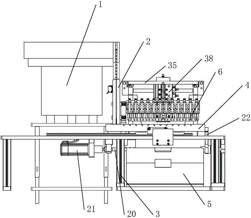
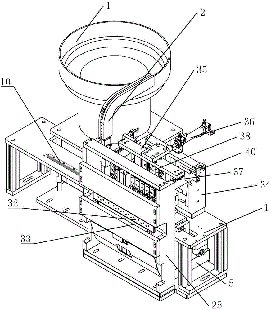
[0040] refer to Figure 1 to Figure 13 As shown, a dropping bucket and conduit assembly mechanism implemented in this case includes a vibrating plate 5, a cylinder front gear 6, a material receiving tool 21, a clamping mechanism, a positioning mechanism and a mounting frame 7, a vibrating plate 5, a clamping mechanism, The material receiving tool 21, the front gear 6 of the cylinder and the positioning mechanism are all installed on the mounting frame 7, the vibrating plate 5 is provided with a discharge track, the discharge track is provided with a feed port 9 and a discharge port 10, and the discharge track The material inlet 9 is connected with the vibrating plate 5, the material outlet 10 is connected with the cylinder front gear 6, a limit device is provided between the cylinder front gear 6 of the discharge track 8, and a stopper for grabbing the cylinder front gear is provided above the cylinder front gear. The clamping mechanism of the dripping funnel 1 on the gear 6, ...


PUM


Abstract

The invention discloses a drip chamber and catheter assembling mechanism. According to the technical key points, the drip chamber and catheter assembling mechanism comprises a vibration disc, an air cylinder front rail, a receiving jig, a clamping mechanism, a positioning mechanism and an installation frame. The vibration disc, the clamping mechanism, the receiving jig, the air cylinder front rail and the positioning mechanism are all installed on the installation frame. The vibration disc is provided with a discharging track. The discharging track is provided with a feed inlet and a discharge outlet. The feed inlet of the discharging track is connected with the vibration disc. The discharge outlet of the discharging track is connected with the air cylinder front rail. A limiting device is arranged between the discharging track and the air cylinder front rail. The clamping mechanism for grabbing a drip chamber on the air cylinder front rail is arranged above the air cylinder front rail. The positioning mechanism can fix a catheter. The clamping mechanism clamps the drip chamber on the receiving jig and the catheter on the positioning mechanism for assembling, a first optical fiber for controlling the limiting device and the clamping mechanism is arranged on the air cylinder front rail, the drip chamber and catheter assembling success rate is improved, and resource waste is reduced.

Description

technical field [0001] The invention belongs to the technical field of medical devices, and more specifically relates to a dripping funnel and catheter assembly mechanism. Background technique [0002] When medical devices are assembled with medical dripping funnels, since the medical dripping funnels are equipped with rubber heads, the shape of the medical dripping funnels is irregular. Although the air filter can be sent to the conveyor belt of the production line more accurately, the work efficiency is relatively low, and the workers have more or less microorganisms such as bacteria, which will pollute the air filter and make the assembled medical equipment clean. Greatly reduced. [0003] As one of the important parts of the infusion set, the medical dripping funnel assembly, such as figure 1 As shown, it generally includes a dropping funnel 1 and a glue head 2; wherein the dropping funnel 1 is in the shape of a circular tube, and one end of the dropping funnel 1 is pr...

Claims


Application Information

Patent Timeline
IPC IPC(8): B23P19/02B23P19/027B23P19/12
CPCB23P19/024B23P19/027B23P19/12
Inventor 梁启明
Owner 梁启明
Learn More