Multi-stirring-mode paint production system powered by adjustable stabilized voltage source
A production system and multi-stirring technology, applied in the direction of mixer accessories, dissolving, mixing machines, etc., can solve the problems of popularization and application troughs, achieve the effects of short processing time, better product quality, and power supply reliability
- Summary
- Abstract
- Description
- Claims
- Application Information
AI Technical Summary
Problems solved by technology
Method used
Image
Examples
Embodiment 1
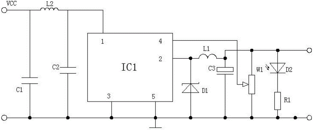
[0039] The multi-stirring mode paint production system powered by an adjustable regulated power supply, when emulsifying and dispersing raw materials, adopts three stirring speeds of high, medium and low to emulsify and disperse raw materials, thereby effectively improving the quality characteristics of the paint. The entire production equipment has a production capacity High efficiency, excellent quality of finished products, etc., and effectively reduce the waste of raw materials and improve the conversion rate of products, such as figure 1 , figure 2 As shown, the following arrangement structure is adopted in particular: including a multi-stirring system reactor 18, a liquid raw material loading device 15, a static mixing system, and a voltage-stabilized power supply circuit for supplying power to the control circuit of the multi-stirring system reactor 18. The piezoelectric power supply circuit is connected to the multi-stirring system reactor 18; the liquid raw material ...
Embodiment 2
[0043] This embodiment is further optimized on the basis of the above embodiments. In order to further realize the present invention better, it is possible to observe whether the power supply is normal in real time while improving the safety and reliability of the power supply of the control circuit, such as figure 1 , figure 2 As shown, the following arrangement structure is particularly adopted: a capacitor C1, a capacitor C2, and an inductor L2 are arranged in the LCπ-type power filter, and the second end of the capacitor C1 and the second end of the capacitor C2 are connected in common and connected to the stable The pin 3 and pin 5 of the pressing chip IC1 are connected to ground, and the first end of the capacitor C1 is connected to the first end of the capacitor C2 and the pin 1 of the voltage stabilizing chip IC1 through the inductance L2; The light emitting diode D2 and the resistor R1, the anode of the light emitting diode D2 is connected to the common junction of t...
Embodiment 3
[0045] This embodiment is further optimized on the basis of any of the above-mentioned embodiments, further in order to better realize the present invention and improve the safety and reliability of power supply of the control circuit, such as figure 1 , figure 2 As shown, the following arrangement structure is particularly adopted: the capacitor C3 is an electrolytic capacitor, and the positive pole of the capacitor C3 is connected to the inductor L1, the negative pole of the voltage regulator tube D1 is connected to pin 2 of the voltage regulator chip IC1, and the voltage regulator Chip IC1 adopts LM2576 series integrated voltage regulator circuit.
PUM
 Abstract
Description
Claims
Application Information
 - R&D
- Intellectual Property
- Life Sciences
- Materials
- Tech Scout
- Unparalleled Data Quality
- Higher Quality Content
- 60% Fewer Hallucinations
Browse by: Latest US Patents, China's latest patents, Technical Efficacy Thesaurus, Application Domain, Technology Topic, Popular Technical Reports.
© 2025 PatSnap. All rights reserved.Legal|Privacy policy|Modern Slavery Act Transparency Statement|Sitemap|About US| Contact US: help@patsnap.com


