Triangular wave modulation photoelectric plethysmography measurement device and method capable of raising electrical level
A technology of photoplethysmography and measuring devices, which is applied in diagnostic recording/measurement, medical science, diagnostic signal processing, etc., can solve the problems of low signal-to-noise ratio of digital signals and affect signal measurement accuracy, so as to improve signal-to-noise ratio and improve The effect of precision
- Summary
- Abstract
- Description
- Claims
- Application Information
AI Technical Summary
Problems solved by technology
Method used
Image
Examples
Embodiment 1
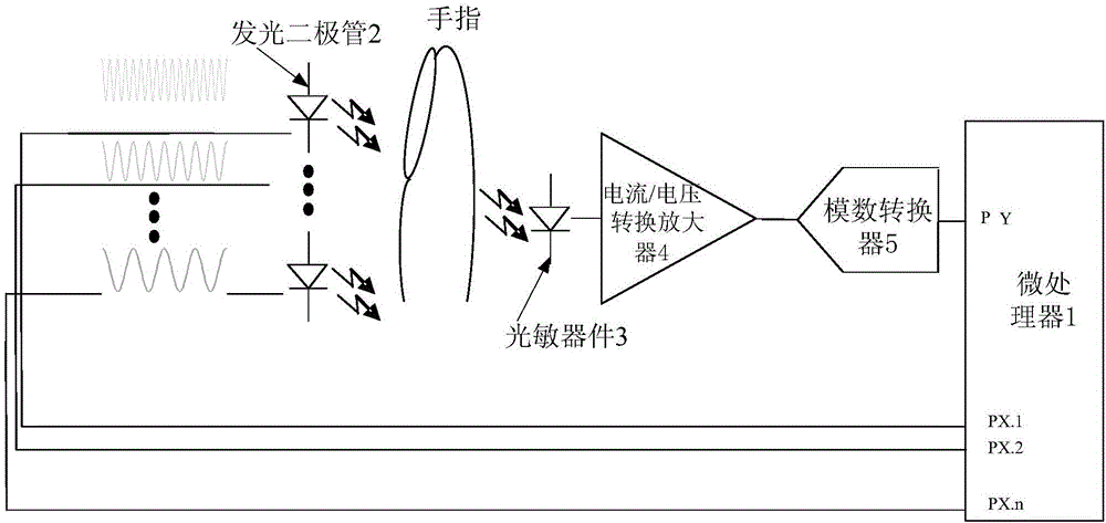
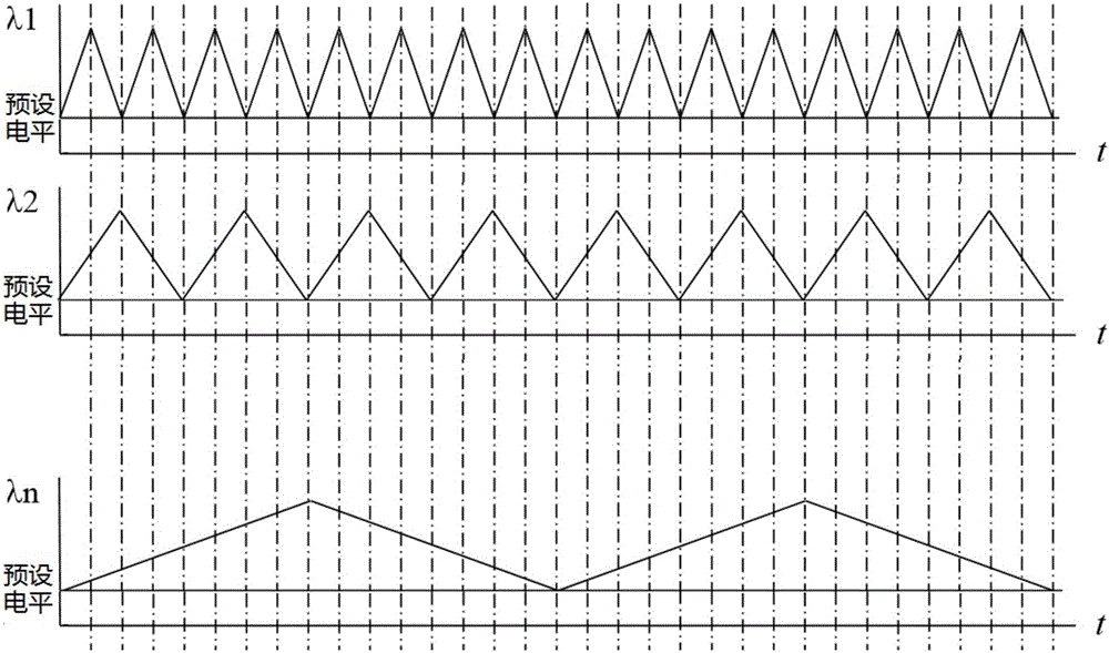
[0046] A triangular wave modulated photoplethysmography measurement device with elevated levels, see figure 1 and figure 2 , the triangular wave modulated photoplethysmography measuring device with raised level comprises: a microprocessor 1, at least four kinds of light emitting diodes 2, a photosensitive device 3, a current / voltage conversion amplifier 4 and an analog-to-digital converter 5,
[0047] Microprocessor 1 outputs triangular waves with different frequencies and a ratio of 2 times of raised preset levels, and the raised triangular waves of preset levels drive at least 4 kinds of light-emitting diodes 2, and the light emitted by light-emitting diodes 2 passes through the finger under test. Received by the photosensitive device 3, the photosensitive device 3 converts it into a voltage signal, and the voltage signal is converted into a preset amplitude voltage signal by the current / voltage conversion amplifier 4.
[0048] After the embodiment of the present invention...
Embodiment 2
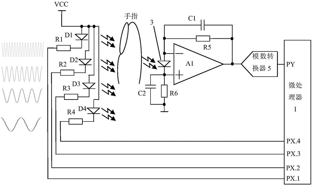
[0064] A triangular wave modulated photoplethysmography measurement device with elevated levels, see image 3 , the measuring device has adopted four kinds of light-emitting diodes 2, and the four I / O ports PX.1, PX.2, PX.3 and PX.4 of the microprocessor 1 respectively pass through the first resistor R1, the second resistor R2, The third resistor R3 and the fourth resistor R4 drive the first light emitting diode D1, the second light emitting diode D2, the third light emitting diode D3 and the fourth light emitting diode D4, the first light emitting diode D1, the second light emitting diode D2, the third light emitting diode The light transmitted by D3 and the fourth light-emitting diode D4 is received by the photosensitive sensor 3, and the signal received by the photosensitive sensor 3 passes through the operational amplifier A1, the first capacitor C1, the second capacitor C2 and the fifth resistor R5. The current / voltage conversion amplifier 4 composed of the sixth resistor...
Embodiment 3
[0068] A kind of triangular wave modulation photoplethysmography measurement method with raised level, see Figure 4 , the method includes the following steps:
[0069] 101: The microprocessor 1 drives at least four kinds of light-emitting diodes 2 by using triangular waves with different frequencies and a ratio of 2 times to increase the preset level;
[0070] 102: The light emitted by the light-emitting diode 2 passes through the finger under test and is received and converted into a voltage signal by the photosensitive device 3, and the voltage signal is amplified into a preset amplitude voltage signal by the current / voltage conversion amplifier 4;
[0071] 103: The preset amplitude voltage signal is converted into a digital signal by the analog-to-digital converter 5 and sent to the microprocessor 1;
[0072] 104: The microprocessor 1 performs phase-locking calculation and separation processing on the digital signal to obtain the photoplethysmography wave and eliminate th...
PUM
 Abstract
Description
Claims
Application Information
 - R&D
- Intellectual Property
- Life Sciences
- Materials
- Tech Scout
- Unparalleled Data Quality
- Higher Quality Content
- 60% Fewer Hallucinations
Browse by: Latest US Patents, China's latest patents, Technical Efficacy Thesaurus, Application Domain, Technology Topic, Popular Technical Reports.
© 2025 PatSnap. All rights reserved.Legal|Privacy policy|Modern Slavery Act Transparency Statement|Sitemap|About US| Contact US: help@patsnap.com


