Display apparatus with scanning and enrolling functions
A display device and function technology, applied in the direction of identification device, image communication, electrical components, etc., can solve the problem of not having the function of scanning and recording
- Summary
- Abstract
- Description
- Claims
- Application Information
AI Technical Summary
Problems solved by technology
Method used
Image
Examples
Embodiment 1
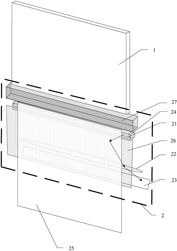
[0037] see figure 1 , the arrows in the figure indicate the direction of light propagation, and the same is true for the following drawings. A display device with a scanning and recording function provided in Embodiment 1 of the present application includes: a display panel 1, and a display panel located in the frame area of the display panel 1. Scanning component 2 (such as figure 1 shown in the dotted box).
[0038] Wherein, the frame area refers to the area around the display panel 1 in the above-mentioned display device with scanning and recording function, for example, as figure 1 As shown, it is located below the display panel 1.
[0039] The display panel 1 can be any type of display panel, such as a liquid crystal display panel (LCD), an organic electroluminescence display panel (OLED), an electrophoretic display panel, a cathode ray tube display panel, a plasma display panel, and the like.
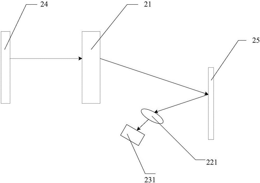
[0040] Such as figure 1 As shown, the scanning component 2 includes: a ...
Embodiment 2
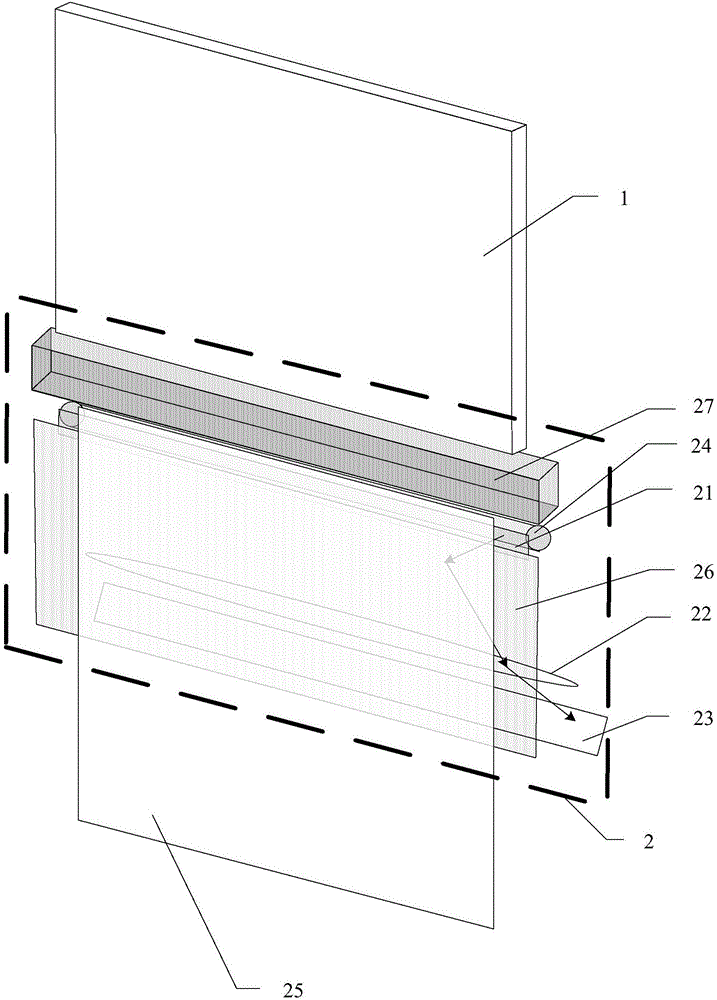
[0051] see image 3 , a display device with a scanning input function provided in Embodiment 2 of the present application is similar to a display device with a scanning input function provided in Embodiment 1 of the present application. different parts.
[0052] Embodiment 2 of the present application provides a display device with scanning input function, such as image 3 As shown, the scanning assembly 2 may further include: a slidable shading plate 26; the incident light source 24 and the shading plate 26 are arranged in sequence along the light emitting direction of the display panel 1, and are used to block the light emitting from the incident light source 24 along the display panel 1 during the non-scanning period. Direction of light emitted. Wherein, the light shielding plate 26 is located on a side of the light guide unit 21 away from the incident light source 24 .
Embodiment 3
[0054] see Figure 4 , the display device with scanning input function provided in the third embodiment of the present application is similar to the display device with the scanning input function provided in the first embodiment of the application, the same parts will not be repeated here, and only the description will be given below different parts.
[0055] Embodiment 3 of the present application provides a display device with scanning input function, such as Figure 4 As shown, the scanning assembly 2 can also include: a beam splitter 28 arranged on the optical path between the scanning object 25 and the focusing lens group 22; the image sensor group 23 includes three rows of image sensors 231 distributed in an array; each row of image sensors 231 is used to receive an optical signal of one color among optical signals of red, green, and blue. Among them, the image sensor 231R ( Figure 5 Only one is shown in ) for receiving the red light signal, the image sensor 231G ( ...
PUM
 Abstract
Description
Claims
Application Information
 - Generate Ideas
- Intellectual Property
- Life Sciences
- Materials
- Tech Scout
- Unparalleled Data Quality
- Higher Quality Content
- 60% Fewer Hallucinations
Browse by: Latest US Patents, China's latest patents, Technical Efficacy Thesaurus, Application Domain, Technology Topic, Popular Technical Reports.
© 2025 PatSnap. All rights reserved.Legal|Privacy policy|Modern Slavery Act Transparency Statement|Sitemap|About US| Contact US: help@patsnap.com


