
Thermal insulation photovoltaic module air floatation location group frame device

A photovoltaic module and air flotation technology, which is applied to electrical components, semiconductor devices, climate sustainability, etc., can solve the impact of thermal insulation photovoltaic module yield and production efficiency, slow progress in research and development of frame devices, and uneven force on the frame, etc. problems, to achieve the effect of improving yield rate and production efficiency, reasonable action, and preventing warping and deformation

Pending Publication Date: 2017-02-15
河南昊诚光电科技有限公司
View PDF0 Cites 1 Cited by
  • Summary
  • Abstract
  • Description
  • Claims
  • Application Information

AI Technical Summary

Problems solved by technology

However, the frame pressing mechanism of the current framing machine uses a group of cylinders for compression. Due to the small size of the compression block installed on the cylinder, it is very easy to cause the frame of the component to bend due to uneven force, especially Especially in the production of thermal insulation photovoltaic modules, due to the installation of thermal insulation materials on the modules, the positioning accuracy of the framing machine is required to be higher. Ordinary framing machines are far from meeting the technical requirements of thermal insulation photovoltaic modules. Due to problems such as uniform force applied to the group frame, large force length, balanced pressing action, and small space for increasing the transmission system, the research and development of the group frame device that can automatically transfer components and have high-precision positioning has been slow. rate and productivity have been greatly impacted

Method used


Image

  • Thermal insulation photovoltaic module air floatation location group frame device
  • Thermal insulation photovoltaic module air floatation location group frame device
  • Thermal insulation photovoltaic module air floatation location group frame device

Examples


Embodiment Construction

[0010] In order to fully explain the implementation of the present invention, the implementation examples of the present invention are provided below, and these implementation examples are only illustrations of the present invention, and do not limit the scope of the present invention.

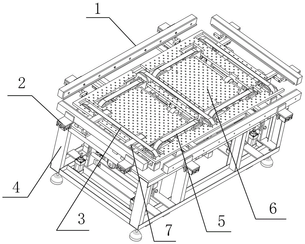
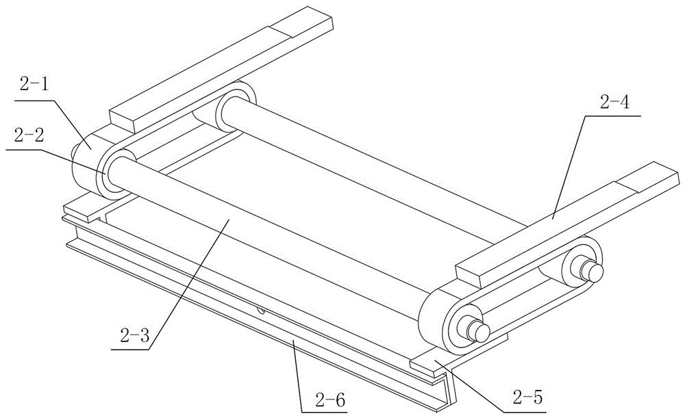
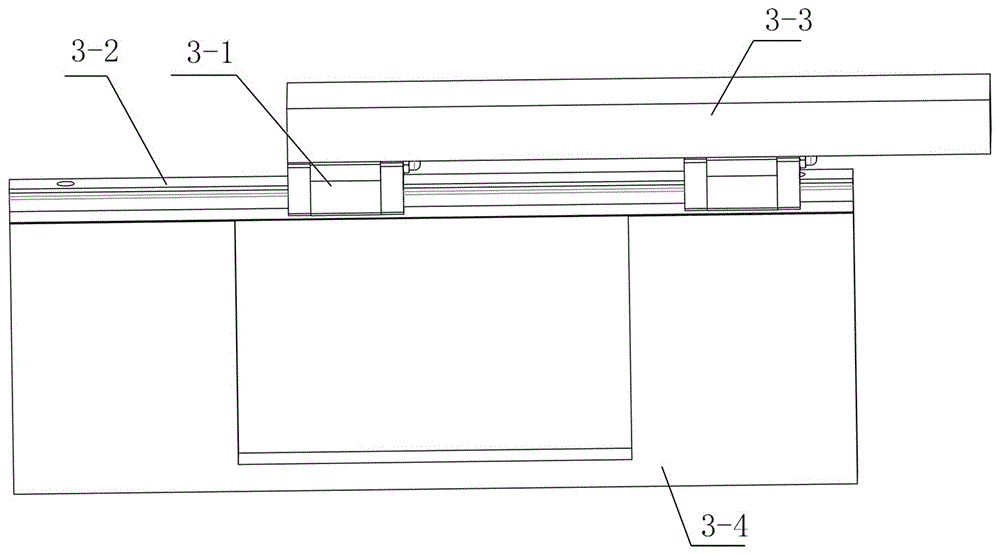
[0011] The present invention is further explained in conjunction with the accompanying drawings. Marked in the drawings: 1. Bead; 2. Photovoltaic module positioning mechanism; 3. Photovoltaic module horizontal transmission device; 4. Rack; 5. Photovoltaic module vertical transmission device; ;2-1. Silent chain; 2-2. Silent sprocket; 2-3. Connecting shaft; 2-4. Bead connecting plate; 2-5. Support; 2-6. Support connecting plate; 3-1 . Slider; 3-2. Guide rail; 3-3. Slider connecting plate; 3-4. Support plate; 4-1. Drive shaft; 4-2. Pulley; 4-3. Belt; 4-4. Belt Body; 4-5. Slide bar; 4-6. Connecting plate; 4-7. Silent chain drive; 4-8. Cylinder; 4-9. Motor. It can be seen from the figure that the...


PUM


Abstract

The present invention relates to a thermal insulation photovoltaic module air floatation location group frame device, belonging to the photovoltaic device manufacturing technology field. The thermal insulation photovoltaic assembly test group frame device for an agriculture glasshouse comprises a long pressing strip, a location mechanism, a short pressing strip, a rack, a cylinder, a pressing strip connecting plate, a silencing chain combination, a sliding blocking guide rail combination, a horizontal transmission system, a longitudinal transmission system and an air-floating platform. The thermal insulation photovoltaic module air floatation location group frame device is safe in structure and reasonable in motion, can flatly perform air floatation and uniform distribution adsorption in the photovoltaic assembly group frame for the agriculture glasshouse and prevent the battery pieces in the assembly from buckling deformation caused by the group frame force so as to reduce the occurrence of the subfissure.

Description

technical field [0001] The invention relates to a photovoltaic group frame positioning device, in particular to an air flotation positioning group frame device for thermal insulation photovoltaic modules, which belongs to the technical field of photovoltaic equipment manufacturing. Background technique [0002] In the production of photovoltaic modules, the framing process of photovoltaic modules is a key process for the final assembly of modules. The photovoltaic module framing machine is a special equipment for screw connection and corner riveting aluminum alloy rectangular frame assembly. After the modules are laminated, By extruding and positioning the aluminum alloy frame of the component, and then using power to fix the aluminum alloy frame and then connect it, the whole process of fixing the aluminum alloy frame and grouping the frame is realized on the same equipment. The application of the automatic framing machine reduces the work intensity of workers, saves produc...

Claims


Application Information

Patent Timeline
IPC IPC(8): H01L21/68H01L31/18
CPCH01L31/18H01L21/68Y02P70/50
Inventor 魏飞董青山张文祥宋付增
Owner 河南昊诚光电科技有限公司
Learn More