Seismic inversion reservoir prediction method based on decompaction acoustic wave velocity

A sonic velocity and seismic inversion technology, applied in seismology, geophysical measurement, seismic signal processing, etc., can solve unreasonable, inability to objectively reflect the initial porosity and compaction process of rock formations, and inability to obtain pore-depth changes function and other issues, to achieve the effect of strong operability and wide application range

Inactive Publication Date: 2017-02-15
XI'AN PETROLEUM UNIVERSITY
View PDF6 Cites 13 Cited by
  • Summary
  • Abstract
  • Description
  • Claims
  • Application Information

AI Technical Summary

Problems solved by technology

The commonly used stratum skeleton volume constant decompaction correction method is theoretically correct, but it is unreasonable to regard the porosity of different rock formations at different depths today as the porosity of the same rock formation at different depths in different geological periods
In addition, the porosity-depth function determined by the statistical regression method often cannot objectively reflect the initial porosity and compaction process of rock formations.
Although some researchers propose to divide formation compaction units according to lithology and stratigraphic age, and then determine the initial porosity and compaction model according to the experimental method, there is still a problem that the real pore-depth variation function cannot be obtained.

Method used


Image

  • Seismic inversion reservoir prediction method based on decompaction acoustic wave velocity
  • Seismic inversion reservoir prediction method based on decompaction acoustic wave velocity
  • Seismic inversion reservoir prediction method based on decompaction acoustic wave velocity

Examples


Embodiment 1

[0039] Example 1. Prediction of Paleozoic Permian tight sandstone reservoirs on the 2D seismic 07YC-EW242 line passing through Well Y454 in Yanchang Gas Field

[0040] A seismic inversion reservoir prediction method based on decompaction acoustic wave velocity, comprising the following steps:

[0041] The first step is to organize and analyze the original acoustic time difference curve

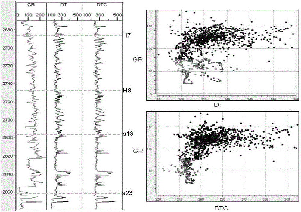
[0042] The acoustic transit time curve of Well Y454 was analyzed, and the target intervals were determined to be the Heba Member and Shanxi Formation in the Lower Shihezi Formation of the Permian. The overall quality of the original acoustic time difference curve is good, and only local outliers need to be processed. For example, the outliers -9999.99 at the top and bottom of the measured depth need to be deleted for subsequent display and speed conversion calculation.

[0043] The second step is to perform time-frequency analysis on the acoustic time-difference curve

[0044] The short-time...

Embodiment 2

[0055] Example 2: Prediction of Paleozoic Permian tight sandstone reservoirs on the 2D seismic YC2011-EW276 line passing through Well Y743 in Yanchang Gas Field

[0056] A seismic inversion reservoir prediction method based on decompaction acoustic wave velocity, comprising the following steps:

[0057] The first step is to organize and analyze the original sound wave velocity curve

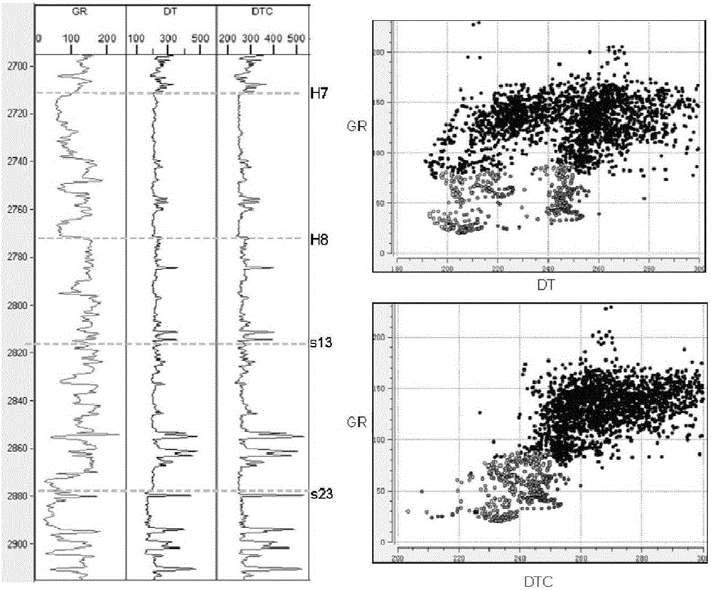
[0058] The acoustic time difference logging curve of Well Y743 was analyzed, and the target intervals were determined to be the Heba Member and Shanxi Formation in the Lower Shihezi Formation of the Permian. The overall quality of the original acoustic transit time curve is good, and only the local outliers need to be de-spiked. For example, there is an outlier 23us / m at 2780.125m. This outlier is very isolated, indicating that it is not caused by lithology, but by early The processing result is artificially abnormal. Reasonable acoustic time difference is obtained after despiking treatment.

...

Embodiment 3

[0071] Example 3. Prediction of Paleozoic Permian tight sandstone reservoirs on the L327 seismic line passing through Well YQ2 in Yanchang Gas Field

[0072] A seismic inversion reservoir prediction method based on decompaction acoustic wave velocity, comprising the following steps:

[0073] The first step is to organize and analyze the original sound wave velocity curve

[0074] The acoustic time difference logging curve of Well YQ2 was analyzed, and the target intervals were determined to be the Heba Member and Shanxi Formation of the Lower Shihezi Formation in the Permian. The overall quality of the original acoustic time difference curve is good, and only local outliers need to be processed. For example, the outliers -9999.99 at the top and bottom of the measured depth need to be deleted for subsequent display and speed conversion calculation.

[0075] The second step is to perform time-frequency analysis on the sound wave velocity curve

[0076] The time-frequency analy...


PUM


Abstract

The invention discloses a seismic inversion reservoir prediction method based on decompaction acoustic wave velocity. First, original acoustic wave velocity time difference data are arranged and analyzed, time frequency analysis processing is performed on the data, low-frequency components and intermediate- and high-frequency components are saved respectively, then a low-frequency acoustic wave time difference curve is corrected according to a low-frequency long trend fine adjustment method, the corrected low-frequency components and the originally saved high-frequency components are fused to obtain a new acoustic wave time difference curve after decompaction correction, accordingly a crossplot analysis method is utilized to perform reservoir response characteristic analysis on the corrected acoustic wave time difference, the reservoir acoustic wave response characteristic is clear, and is then converted into acoustic wave velocity as a characteristic curve to carry out reservoir multi-attribute neural network seismic inversion treatment, thereby obtaining an acoustic wave velocity invertomer, and finally, a seismic and geological comprehensive assessment means is adopted to carry out explanation and analysis on the acoustic wave velocity invertomer, thereby obtaining a reservoir qualitative and quantitative prediction result. The seismic inversion reservoir prediction method based on decompaction acoustic wave velocity has the advantages of strong operability and wide application range.

Description

【Technical field】 [0001] The invention relates to the field of oil exploration reservoir prediction, in particular to a seismic inversion reservoir prediction method based on decompression sound wave velocity. 【Background technique】 [0002] Reservoir inversion is a key technical means to realize quantitative analysis and evaluation of reservoirs in the process of reservoir prediction. When carrying out reservoir inversion, seismic data and logging acoustic velocity data are two types of basic data that are necessary. Practice shows that the quality of basic data has a decisive impact on the results of reservoir inversion and reservoir prediction. The quality of seismic data mainly includes two important attributes: signal-to-noise ratio and resolution. Among them, the factor of signal-to-noise ratio affects the recovery degree of effective seismic inversion signals, while the resolution determines the identification of vertical thickness and lateral shape of seismic invers...

Claims


Application Information

Patent Timeline
IPC IPC(8): G01V1/30
CPCG01V1/306
Inventor 赖生华王念喜乔向阳王永炜梁全胜曹鉴华
Owner XI'AN PETROLEUM UNIVERSITY
Why Eureka
Try Eureka