Apparatus for injecting tail gas and inflow hot air in vacuum cabin of ramjet

A technology for ramjets and vacuum chambers, which is used in the testing of engines, measuring devices, and testing of machine/structural components. Test site, compact structure, high vacuum effect

Inactive Publication Date: 2017-02-15
XIAN AEROSPACE PROPULSION TESTING TECHN INST
View PDF4 Cites 4 Cited by
  • Summary
  • Abstract
  • Description
  • Claims
  • Application Information

AI Technical Summary

Problems solved by technology

This method cannot meet the goal of long-term testing when simulating a large amount of incoming air, and it is difficult to maintain a stable pressure in the vacuum chamber

Method used


Image

  • Apparatus for injecting tail gas and inflow hot air in vacuum cabin of ramjet
  • Apparatus for injecting tail gas and inflow hot air in vacuum cabin of ramjet

Examples


Embodiment approach

[0025] The best implementation mode of the present invention is as follows:

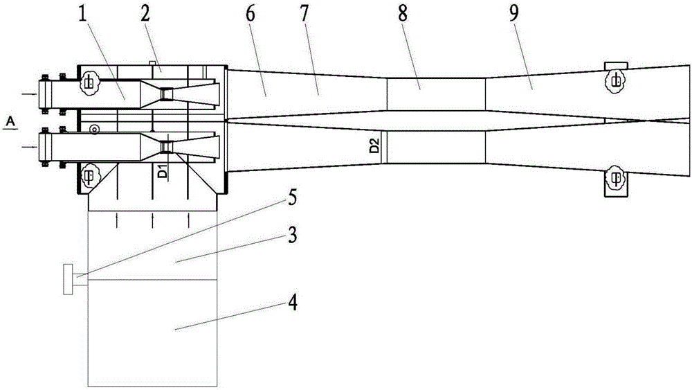
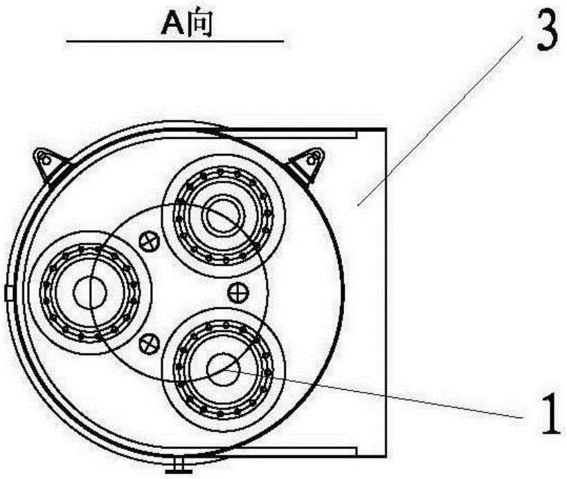
[0026] see figure 1 with figure 2 As shown, in the exhaust gas and incoming hot air injection device in the vacuum chamber of the ramjet, three injection nozzles 1 are inserted into the receiving chamber 2 at intervals of 120°, and the side of the receiving chamber 2 is connected to the vacuum pipe 3, and the vacuum pipe 3 is connected to the vacuum of the ramjet. The cabins 4 are connected, separated by a vacuum butterfly valve 5 in the middle, and the outlets of the three injection nozzles 1 are respectively connected with the three throttling pipes 6 (the three throttling pipes all include the mixing chamber 7, the connecting pipe 8 and the diffusion chamber 9 connected in sequence. ); Before the engine is ignited, the steam first passes into three injection nozzles 1, and because the cross-sectional area of ​​the flow passage decreases, a negative pressure is generated at the outlet of the inje...


PUM


Abstract

The invention belongs to the technical field of ramjet test, and specifically relates to an apparatus for injecting the tail gas and inflow hot air in a vacuum cabin of a ramjet. The apparatus comprises a receiving chamber, a vacuum pipeline, a vacuum butterfly valve, an injection nozzle and a throttle pipeline, wherein the injection nozzle is of a De-Laval nozzle structure and is inserted in the receiving chamber, the inlet of the injection nozzle is exposed outside the receiving chamber for receiving external high-temperature steam, the outlet of the injection nozzle is positioned in the receiving chamber and communicates with the inlet of the throttle pipeline, and the vacuum pipeline is installed on the side surface of the receiving chamber and connected with the vacuum cabin of the ramjet through the vacuum butterfly valve. The apparatus can satisfy long-time test and stably retain pressure in the vacuum cabin.

Description

technical field [0001] The invention belongs to the technical field of ramjet testing, in particular to a device for ejecting exhaust gas and incoming hot air in a vacuum chamber of a ramjet. Background technique [0002] The ramjet is an air jet engine that is simple in structure but can generate a lot of thrust and is suitable for high-altitude and high-speed flight. In the development test of the ramjet engine, in order to truly simulate the high-altitude environment, it is necessary to eject the exhaust gas generated by the engine in the vacuum cabin and the simulated incoming high-temperature air to the outside of the cabin to maintain a certain degree of vacuum in the cabin. [0003] The method most adopted at present is the method of the vacuum spherical tank, uses the vacuum pump to pump the spherical tank to a certain degree of vacuum, and utilizes the vacuum degree of the spherical tank to suck the gas in the vacuum chamber into the spherical tank. This method can...

Claims


Application Information

Patent Timeline
Patent Type & Authority Applications(China)
IPC IPC(8): G01M15/02
CPCG01M15/02
Inventor 邹伟龙赵建军王乃世寇兴华李陆昊罗军侯健史超贺宏赵政社刘永伟朱小江黄立还
Owner XIAN AEROSPACE PROPULSION TESTING TECHN INST
Why Eureka
Try Eureka