
Working method of metallurgy cooling mechanism controlled by control system

A technology of cooling mechanism and working method, which is applied in the field of metallurgy, can solve the problems of residual water accumulation in blanks, low cooling efficiency, scrapped blanks, etc., and achieve the effects of low surface humidity, reduced energy consumption, and accelerated drying

Active Publication Date: 2017-02-15
佛山市南海笳恩压铸自动化有限公司
View PDF6 Cites 0 Cited by
  • Summary
  • Abstract
  • Description
  • Claims
  • Application Information

AI Technical Summary

Problems solved by technology

[0002] In the field of metallurgy, many blanks produced, such as pipeline steel, require sufficient and rapid cooling. The traditional cooling method has low cooling efficiency and is likely to cause uneven cooling of the blank, which seriously affects the quality of the blank. Even The blank is scrapped, and the existing technology provides a water shower system for rapid cooling, but after water cooling, there will be residual water on the blank, which will affect the quality of the blank and subsequent processes

Method used


Image

  • Working method of metallurgy cooling mechanism controlled by control system
  • Working method of metallurgy cooling mechanism controlled by control system

Examples


Embodiment Construction

[0015] The principles and features of the present invention are described below in conjunction with the accompanying drawings, and the examples given are only used to explain the present invention, and are not intended to limit the scope of the present invention.

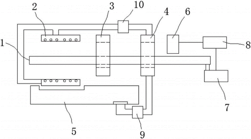
[0016] like figure 1 and figure 2 As shown, a metallurgical cooling mechanism with low humidity includes a conveyor belt 1, two spray devices 2, a water removal device 3, a drying device 4 and a water collection tank 5, and the two spray devices 2 are respectively placed in the Above and below the conveyor belt 1, the water collection tank 5 is placed under the spray device 2 below the conveyor belt 1, and the dewatering device 3 and the drying device 4 are both set on the conveyor belt 1 The outer ring, and the dewatering device 3 is at the rear of the two spraying devices 2, the drying device 4 is at the rear of the dewatering device 3, the water outlet of the sump 5 is connected to the drying The water inlet o...


PUM


Abstract

The invention relates to a working method of a metallurgy cooling mechanism controlled by a control system. The metallurgy cooling mechanism comprises a conveying belt, two spraying devices, a water removal device, a drying device and a water collection tank, wherein the two spraying devices are arranged above and below the conveying belt respectively, the water collection tank is arranged below the spraying device below the conveying belt, the water removal device and the drying device are installed on the outer ring of the conveying belt in a sleeving mode, a water outlet of the water collection tank communicates with a water inlet of the drying device through a pipeline, a water outlet of the drying device communicates with the two spraying devices through pipelines, the drying device is a spiral water pipe, a humidity sensor is arranged on the side, away from the water removal device, of the drying device, a motor is arranged on one side of the conveying belt and drives the conveying belt to operate through a transmission device, the humidity sensor is connected to a control system through a line, and the control system is connected to the motor through a line. Compared with the prior art, the metallurgy cooling mechanism has the advantages that water is recycled, blanks are cooled fast and the surface humidity of the blanks is low.

Description

technical field [0001] The invention relates to the technical field of metallurgy, in particular to a metallurgical cooling mechanism with low humidity. Background technique [0002] In the field of metallurgy, many blanks produced, such as pipeline steel, require sufficient and rapid cooling. The traditional cooling method has low cooling efficiency and is likely to cause uneven cooling of the blank, which seriously affects the quality of the blank. Even The blank is scrapped, and the existing technology provides a water shower system for rapid cooling, but after water cooling, there will be residual water on the blank, which will affect the quality of the blank and subsequent processes. Contents of the invention [0003] The technical problem to be solved by the present invention is to provide a metallurgical cooling mechanism with water recycling, rapid cooling of blanks and low surface humidity of blanks. [0004] The technical scheme of the present invention to solve...

Claims


Application Information

Patent Timeline
Patent Type & Authority Applications(China)
IPC IPC(8): F27D15/02
CPCF27D15/02
Inventor 不公告发明人
Owner 佛山市南海笳恩压铸自动化有限公司
Learn More