A spiral micro-rib water cooling device for laser cladding nozzles

A technology of laser cladding nozzles and cladding nozzles, which is applied in metal material coating process, coating, etc., can solve the problems of laser cladding nozzle temperature rise, great influence on cladding quality, and not obvious cooling effect, etc. , to achieve the effect of improving cladding effect, increasing safety and reliability, and simple structure

Inactive Publication Date: 2018-11-09
NORTHWESTERN POLYTECHNICAL UNIV
View PDF4 Cites 0 Cited by
  • Summary
  • Abstract
  • Description
  • Claims
  • Application Information

AI Technical Summary

Problems solved by technology

[0003] At present, in the laser cladding system, most laser cladding powder feeding systems use laser cladding nozzles for powder feeding. The service life of laser cladding nozzles has a great influence on cladding quality. The distance is very close, and it is easily affected by the thermal radiation of the molten pool and the reflection of the laser, which affects the rapid rise of the temperature of the laser cladding nozzle, so the requirement for the laser cladding nozzle must have a very good cooling effect
[0004] In the patent CN1570190A, "a built-in laser cladding nozzle" is proposed. The cooling effect in the structure of the laser cladding nozzle is realized by the built-in cooling water ring connected to the cooling water circuit in the bottom wall of the conical cylinder. Although the cooling The water ring is placed in the bottom wall of the cone-shaped cylinder, but since its inlet is opened at the upper end of the cone-shaped cylinder, the cooling effect for the high-temperature zone of the laser cladding nozzle, that is, the bottom of the laser cladding nozzle is not obvious; in addition , the nozzle structure is assembled from multiple parts, the overall structure is complex, and it is easy to affect the powder feeding effect or cause water leakage due to improper assembly

Method used


Image

  • A spiral micro-rib water cooling device for laser cladding nozzles
  • A spiral micro-rib water cooling device for laser cladding nozzles
  • A spiral micro-rib water cooling device for laser cladding nozzles

Examples


Embodiment Construction

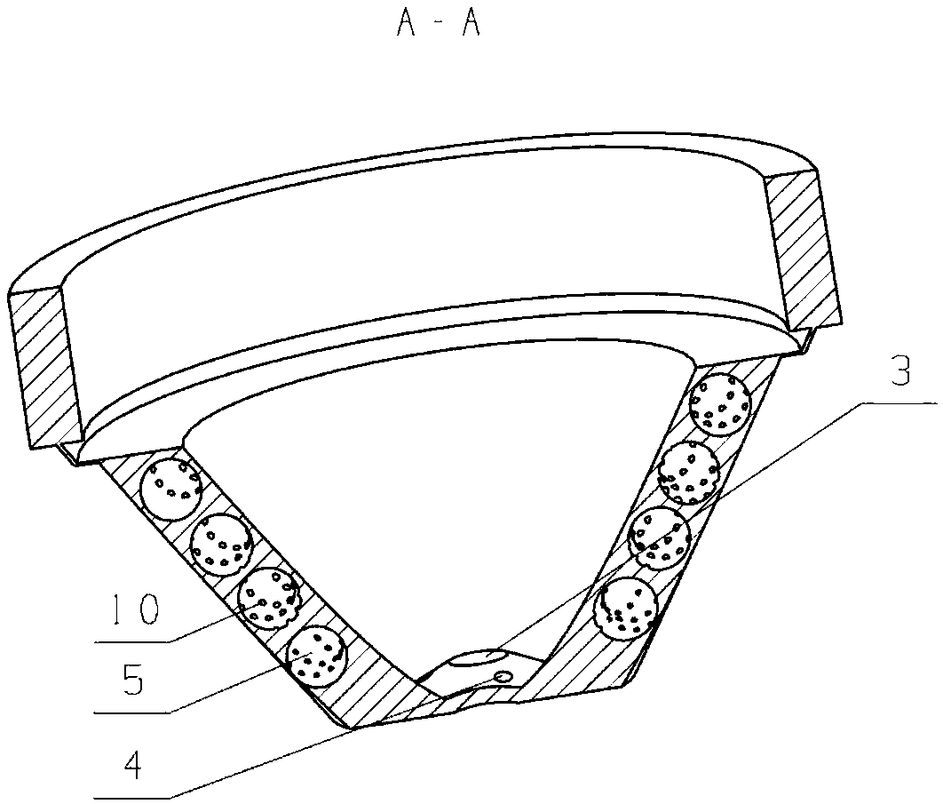
[0027] This embodiment is a spiral micro-ribbed water cooling device for laser cladding nozzles.

[0028] refer to Figure 1 to Figure 8 , the spiral micro-ribbed water cooling device used in the laser cladding nozzle in this embodiment is composed of a water-cooled cone sleeve 8 and a cladding nozzle 9; wherein, the water-cooled cone sleeve 8 also includes an annular channel 5, an arc convex rib 10, and a connecting channel 11 , water outlet 1, water inlet 2, laser hole 3, powder feeding hole 4; the water-cooled cone sleeve 8 is an inverted cone with an integral structure of a ring and a cone. Located at the lower part of the cladding nozzle 9, the water-cooling cone sleeve 8 and the cladding nozzle 9 are connected by thread; the central axis of the water-cooling cone sleeve 8 coincides with the central axis of the cladding nozzle 9, and the structure of the water-cooling cone sleeve 8 is completely clad. Bottom of sprinkler.

[0029] There is an annular channel 5 in the wa...


PUM


Abstract

The invention discloses a spiral micro-fin water cooling device for a laser cladding nozzle. The spiral micro-fin water cooling device is composed of a water cooling taper sleeve and the cladding nozzle. The water cooling taper sleeve is located on the lower portion of the cladding nozzle and connected with the cladding nozzle through threads in a matched mode. A plurality of layers of annular channels are arranged in the wall of the water cooling taper sleeve. The annular channels are increased upwards layer by layer around the cladding nozzle in the axial direction. The annular channels of each layer communicate with one another through connection channels. Arc-shaped convex ribs are arranged on the inner wall faces of the annular channels and used for reinforcing heat exchange and cooling. A laser hole and powder feeding holes are formed in the bottom of the water cooling taper sleeve, and the laser hole and the powder feeding holes communicate with a laser channel and powder feeding channels of the cladding nozzle correspondingly. In the working process, an external water supply system supplies cooling water through a water inlet of the water cooling taper sleeve, and the cooling water flows through the annular channels layer by layer from the bottom and is pumped out from a water outlet of the water cooling taper sleeve. The cladding nozzle is wrapped with the water cooling taper sleeve structure, the cladding nozzle is protected through heat conduction, and laser bounce and thermal radiation of a molten bath are blocked; and temperature control and heat dissipation functions of the cladding nozzle are achieved through the annular channels and the arc-shaped convex rib structures, and the application effect of the cladding nozzle is improved.

Description

technical field [0001] The invention relates to laser processing and cooling technology of high-temperature parts, in particular to a spiral micro-ribbed water cooling device for laser cladding nozzles. Background technique [0002] Laser cladding technology emerged in the 1980s. It is an advanced technology for strengthening, improving and repairing the surface of metal parts. The surface of the substrate is completely melted to form a surface coating with a very low dilution and a metallurgical combination of the substrate material. Laser cladding technology has attracted more and more attention due to its advantages of saving rare metals, improving the surface properties of materials, protecting the environment and reducing energy consumption. [0003] At present, in the laser cladding system, most laser cladding powder feeding systems use laser cladding nozzles for powder feeding. The service life of laser cladding nozzles has a great influence on cladding quality. The...

Claims


Application Information

Patent Timeline
Patent Type & Authority Patents(China)
IPC IPC(8): C23C24/10
CPCC23C24/10
Inventor 刘存良叶林李琳
Owner NORTHWESTERN POLYTECHNICAL UNIV
Why Eureka
Try Eureka