Printing and dyeing wastewater treating system

A treatment system and technology for printing and dyeing wastewater, applied in the textile industry wastewater treatment, water treatment parameter control, biological water/sewage treatment, etc. , It is difficult to completely realize the complete set of technologies for the wastewater treatment system, so as to achieve the effect of shortening the reaction treatment time, reducing the floor space and construction investment, and shortening the treatment time.

Pending Publication Date: 2017-02-15
广东联和环保科技有限公司
View PDF18 Cites 2 Cited by
  • Summary
  • Abstract
  • Description
  • Claims
  • Application Information

AI Technical Summary

Problems solved by technology

[0005] However, compared with small and medium-sized printing and dyeing enterprises that account for most of the production capacity of the printing and dyeing industry, the composition and volume of wastewater are affected by changes in raw materials, seasons, market demand, etc., resulting in large fluctuations in water quality and volume from time to time, all of which have great impact on existing printing and dyeing wastewater treatment systems This will bring adverse effects on the work efficiency, which is especially prominent for small and medium-sized printing and dyeing enterprises that mainly undertake processing business
Therefore, the existing printing and dyeing wastewater treatment system is not ideal for the wastewater treatment of small and medium-sized printing and dyeing enterprises
[0006] Moreover, small and medium-sized printing and dyeing enterprises are also limited by project budgets and limited sites, and it is difficult to fully realize the complete set of technologies of the existing wastewater treatment system. Therefore, the development of economical and effective small and medium-sized printing and dyeing wastewater treatment technologies has become the focus of the printing and dyeing industry.

Method used


Image

  • Printing and dyeing wastewater treating system

Examples


Embodiment Construction

[0024] The specific embodiments of the present invention will be described below in conjunction with the accompanying drawings.

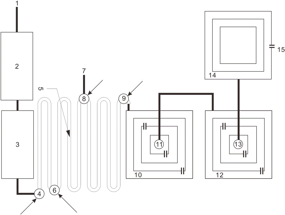
[0025] As shown in the figure, the printing and dyeing wastewater treatment system of the present invention includes a grid oil filter tank 2, a sump tank 3, a regulating reaction pipeline group 5, an acid hydrolysis tank 10, a biochemical tank 12, and a sedimentation tank 14.

[0026] The waste water produced by printing and dyeing equipment is divided into medium and heavy waste water 1 and light waste water 7 according to the pollution concentration. The medium and heavy waste water 1 is first treated by the grid oil filter tank 2 to filter out suspended debris and slick oil, and then enter the sump through pipelines 3. The water outlet of the sump 3 is connected to the first feed adjustment pump 4, and the first feed adjustment pump 4 mixes the reaction agent with the waste water in the sump 3 and pumps it into the adjustment reaction pipe group ...


PUM


Abstract

The invention discloses a printing and dyeing wastewater treating system. The printing and dyeing wastewater treating system comprises a grille oil filter pool, a water collecting pool, a regulating reaction pipeline group, an acidolysis pool, a biochemical pool and a settling pool which are connected in sequence, wherein the regulating reaction pipeline group is provided with multiple feeding regulating pumps; the acidolysis pool and the biochemical pool are of multi-layer hollow square embedding structures, water inlets in each layer are all arranged in diagonal positions of water inlets in the upper layer, and water pumps are arranged in the center of the acidolysis pool and the biochemical pool. According to the printing and dyeing wastewater treating system disclosed by the invention, reaction agents can be fed at different time periods through the feeding regulating pumps, dividing and grading treatment on wastewater in different pollution degrees is realized, the agent dosage is reduced, and the printing and dyeing wastewater treating system is enabled to work at an optimal setting state; the structure is simple, the land is saved, and the printing and dyeing wastewater treating system accord with economic benefit.

Description

technical field [0001] The invention relates to a wastewater treatment system, in particular to a printing and dyeing wastewater treatment system for treating the wastewater discharged from the printing and dyeing process in the textile industry. Background technique [0002] The wastewater discharged from the printing and dyeing process in the textile industry is a medium organic wastewater, and it is recognized as one of the most difficult industrial wastewater to treat. It has complex components and poor biochemical properties. [0003] The existing printing and dyeing wastewater treatment system is a large-scale site treatment system composed of multiple structures such as reaction pools or reaction towers with different functions, as well as supporting equipment and facilities such as water pumps and pipelines. The floor area and construction soil cubic are more than thousands of units. [0004] Due to the large construction scale, the above large-scale printing and dye...

Claims


Application Information

Patent Timeline
Patent Type & Authority Applications(China)
IPC IPC(8): C02F9/14C02F103/30C02F101/30
CPCC02F9/00C02F3/00C02F1/40C02F2101/308C02F2001/007C02F3/28C02F2103/30C02F2209/06C02F2203/006
Inventor 苟亚松
Owner 广东联和环保科技有限公司
Why Eureka
Try Eureka