
Automatic stamping equipment for internal shrinkage film material

A technology of stamping equipment and film materials, which is applied in the field of automatic stamping equipment for shrink film materials, can solve the problems of low production efficiency, failure to meet high-performance precision requirements, and low product yield, and achieve resource saving, uniform quality, and high The effect of economic benefits

Inactive Publication Date: 2017-02-15
昆山维嘉益材料科技有限公司
View PDF6 Cites 1 Cited by
  • Summary
  • Abstract
  • Description
  • Claims
  • Application Information

AI Technical Summary

Problems solved by technology

[0004] In recent years, with the development of the electronic information industry, the requirements for the precision of electronic products are getting higher and higher, and the requirements for the precision and quality uniformity of the corresponding electronic components are getting higher and higher, while the traditional manual or jig It is difficult to meet this requirement for assembly (attachment), and the yield rate of the product is low and the production efficiency is not high
Especially for the production of high-precision shrink-in coil products, the frame must be shrinked, and the product supermodel is getting smaller and smaller. However, the traditional fixture positioning and manual lamination cannot meet its high-performance precision requirements.

Method used


Image

  • Automatic stamping equipment for internal shrinkage film material
  • Automatic stamping equipment for internal shrinkage film material

Examples


Embodiment Construction

[0020] The following will clearly and completely describe the technical solutions in the embodiments of the present invention. Obviously, the described embodiments are only some of the embodiments of the present invention, rather than all the embodiments. Based on the embodiments of the present invention, all other embodiments obtained by persons of ordinary skill in the art without making creative efforts belong to the protection scope of the present invention.

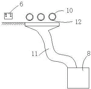
[0021] Such as figure 1 , figure 2 The automatic stamping equipment for shrink film roll material shown in the figure includes a punch feeder 1, a laminating mechanism 2, a pressing machine 3, a waste discharge mechanism 4, a punch press 5, a film covering mechanism 6, and a material receiving mechanism in sequence from front to back 7 and a waste collection mechanism 8, the punch discharge mechanism 1 is set as a drum-shaped discharge device, and the shrinkage roll material to be processed is curled on it, and the...


PUM


Abstract

The invention discloses automatic stamping equipment for an internal shrinkage film material. The automatic stamping equipment comprises a punch discharging machine, a fitting mechanism, a press attaching machine, a waste discharge mechanism, a punch, a film covering mechanism, a receiving mechanism and a waste collection mechanism from front to back sequentially; the punch discharging machine is arranged to be a drum-shaped discharging device, the internal shrinkage film material to be processed is shrunk on the punch discharging machine, and the punch discharging machine is arranged on the punch and synchronously operates with a transmission mechanism of the punch under the control of a servo motor; a die cutting mechanism matched with a die cutting product comprises a die cutting knife and is arranged on the press attaching machine, and the die cutting knife is controlled by the servo system and synchronously operates with the punch discharging machine. The automatic stamping equipment for the internal shrinkage film material, disclosed by the invention, has the benefits that the production efficiency and the product quality are improved, the uniform quality is ensured, resources are saved, the cost is reduced, and product production accuracy requirements are met.

Description

[0001] Technical field: [0002] The invention relates to an automatic punching equipment for shrink film roll materials. [0003] Background technique: [0004] In recent years, with the development of the electronic information industry, the requirements for the precision of electronic products are getting higher and higher, and the requirements for the precision and quality uniformity of the corresponding electronic components are getting higher and higher, while the traditional manual or jig Assembly (attachment) has been difficult to meet this requirement, and the yield rate of the product is low and the production efficiency is not high. Especially for the production of high-precision shrink-in coil products, the frame must be shrinked, and the product supermodel is getting smaller and smaller. However, the traditional fixture positioning and manual lamination cannot meet its high-performance precision requirements. . [0005] Invention content: [0006] The technical ...

Claims


Application Information

Patent Timeline
IPC IPC(8): B32B37/00B32B37/06B32B38/00
CPCB32B37/0046B32B37/06B32B38/0004
Inventor 夏玉龙凌丽平
Owner 昆山维嘉益材料科技有限公司
Learn More