
Fiber laser machining device

A fiber laser and processing device technology, used in laser welding equipment, metal processing equipment, manufacturing tools, etc., can solve the problems of incompact structure of the processing device, inability to observe the laser and processing samples in real time, and the processing platform having no movement adjustment function, etc. achieve compact structure

Active Publication Date: 2017-02-15
PUTIAN UNIV
View PDF10 Cites 2 Cited by
  • Summary
  • Abstract
  • Description
  • Claims
  • Application Information

AI Technical Summary

Problems solved by technology

[0003] Therefore, it is necessary to provide a fiber laser processing device to solve the problems that the current existing laser processing devices cannot observe the laser and the processed samples in real time, the structure of the processing device is not compact, and the processing platform has no mobile adjustment function.

Method used


Image

  • Fiber laser machining device
  • Fiber laser machining device

Examples


Embodiment Construction

[0042] In order to explain in detail the technical content, structural features, achieved goals and effects of the technical solution, the following will be described in detail in conjunction with specific embodiments and accompanying drawings.

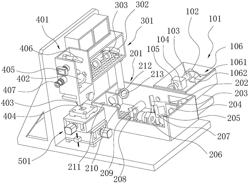
[0043] Please also refer to figure 1 and figure 2 , figure 1 It is a structural schematic diagram of the fiber laser processing device of the present embodiment. The fiber laser device 101 is provided with a pumping light source 102, an optical fiber 103, a resonant cavity 104, a laser amplifier 105 and a water cooling device 106. One end of the optical fiber 103 is connected to the pumping light source 102. One end is connected to the resonant cavity 104, the laser amplifier 105 is arranged on the laser optical path of the resonant cavity 104, and the liquid circulation pipeline 1061 of the water cooling device 106 is connected to the pumping light source 102 and the delivery pump 1062;

[0044] The horizontal optical path device ...


PUM


Abstract

The invention discloses a fiber laser machining device which sequentially comprises a fiber laser device, a horizontal light path device, a vertical light path device, a laser machining device and a machining platform in the light path direction of laser. By means of a probe arranged in the horizontal light path device and a micro camera arranged in the laser machining device, the state of laser beams and samples can be observed in real time. By means of a first reflecting mirror, a second reflecting mirror, a third reflecting mirror, a fourth reflecting mirror and a fifth reflecting mirror arranged in the horizontal light path device, devices, located among the reflecting mirrors, in the horizontal light path device are arranged reasonably, and the structure of the machining device is more compact. As sliding platforms in the X, Y and Z directions are arranged on the machining platform, the machining platform can be moved and adjusted in the machining process.

Description

technical field [0001] The invention relates to the field of laser processing, in particular to an optical fiber laser processing device. Background technique [0002] With the improvement of laser processing technology and the expansion of application scope, laser processing is becoming more and more popular in production activities, but the existing laser processing device cannot observe the optical path of the laser and the processed sample in real time, and the optical components in the laser processing device There are many, the position is fixed, it takes up a lot of space, and it is not easy to move, and most of the processing platforms are single fixed, without adjustment function. Contents of the invention [0003] Therefore, it is necessary to provide a fiber laser processing device to solve the problems that the existing laser processing device cannot observe the laser and the processed sample in real time, the structure of the processing device is not compact, ...

Claims


Application Information

Patent Timeline
Patent Type & Authority Applications(China)
IPC IPC(8): B23K26/064B23K26/08B23K26/70B23K26/03
CPCB23K26/032B23K26/064B23K26/0643B23K26/0861B23K26/702
Inventor 陈庆堂
Owner PUTIAN UNIV
Learn More