
Manufacturing process and structure of a spiral channel sand core mold for water-cooled motor casings of new energy vehicles

A new energy vehicle, sand core mold technology, applied in the direction of manufacturing tools, cores, casting molding equipment, etc., can solve the problem that the spiral water cooling channel cannot be formed normally, the structure of the water channel sand core mold is unstable, and the motor shell is easy to disperse, etc. problems, to achieve the effect of long storage time, fast molding and curing speed, and not easy to fall apart

Active Publication Date: 2020-06-09
惠州古川科技有限公司
View PDF6 Cites 0 Cited by
  • Summary
  • Abstract
  • Description
  • Claims
  • Application Information

AI Technical Summary

Problems solved by technology

The traditional process of producing motor housings with water-cooling structures is to pour molten aluminum into a die-casting mold, which is pre-installed with a water channel sand core mold, and the die-casting machine works to die-cast the motor housing with spiral water-cooling channels to form, and then After simple heat treatment and machining, it can be used directly. Therefore, the water channel sand core mold is very important for the forming of the spiral water cooling channel. The existing water channel sand core mold has an unstable structure and is not resistant to high temperature, and it is easy to loose when casting the motor casing. Open, resulting in the spiral water cooling channel can not be formed normally

Method used


Image

  • Manufacturing process and structure of a spiral channel sand core mold for water-cooled motor casings of new energy vehicles
  • Manufacturing process and structure of a spiral channel sand core mold for water-cooled motor casings of new energy vehicles
  • Manufacturing process and structure of a spiral channel sand core mold for water-cooled motor casings of new energy vehicles

Examples


Embodiment Construction

[0024] Below in conjunction with accompanying drawing, the specific embodiment of the present invention is described further:

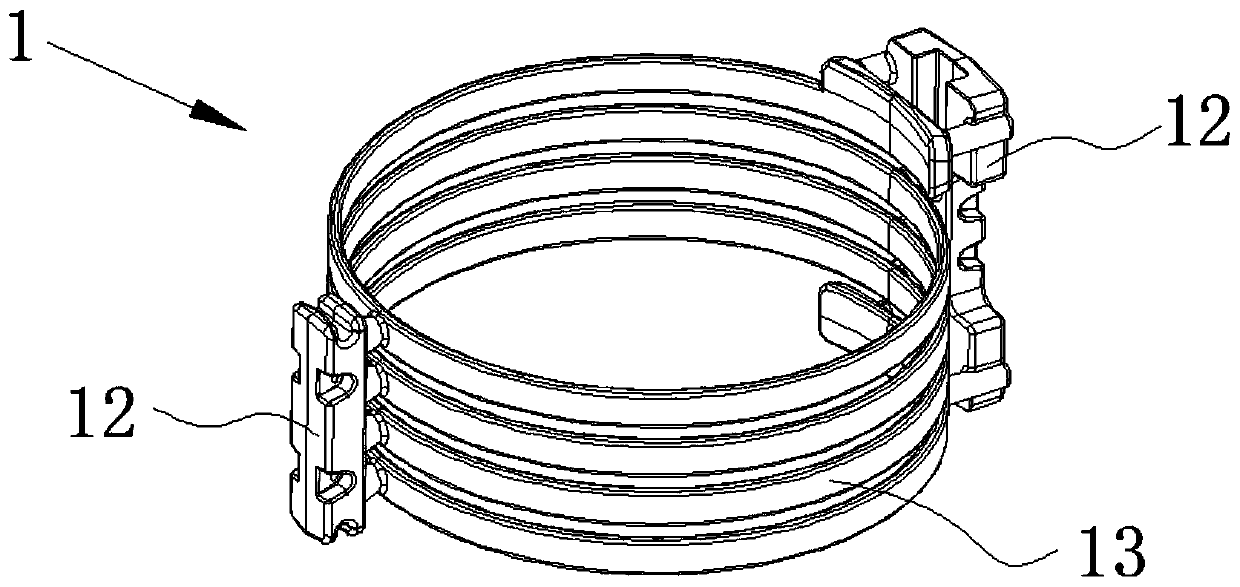
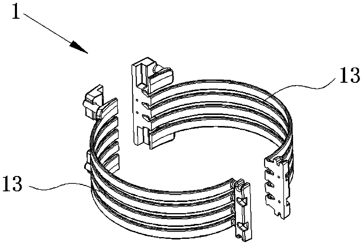
[0025] Such as figure 1 and figure 2 As shown, a new energy vehicle water-cooled motor casing spiral water channel sand core mold manufacturing process, the water channel sand core mold 1 is assembled from two semicircular sand core parts, followed by the following steps,

[0026] (a) Add raw materials, make from 70 to 85% AL 2 o 3 , 3~20%SiO2 2 , 1 ~ 3.5% TiO2 mixed pearl sand into the material box of the core shooter;

[0027] (b) Core-shooting molding, the core-shooting mold is heated to 160-200°C, the core-shooting pressure is 0.4-0.6Mpa, the core-shooting time is 3-5s, and the semicircular sand core is initially formed in the core-shooting mold;

[0028] (c) Curing molding, the semicircular sand core is divided into three stages of curing in the core shooting mold, the first stage of curing temperature is 160-180°C and the time is 50s, the ...


PUM


Abstract

The invention relates to a manufacturing process and a structure for a sand core mold of a spiral water channel of a new energy water-cooled motor enclosure. The manufacturing process comprises the following steps of: (a) adding a raw material: adding fused ceramsite into a workbin of a core shooting machine; (b) performing core shooting forming; (c) performing curing forming, a semi-circular sand core part is cured in three sections; (d) performing cooling; (e) repeating steps (a)-(d) to manufacture another semi-circular sand core part; (f) performing splicing: fixedly splicing the two semi-circular sand core parts together to form the sand core mold of the water channel; and (g) performing packaging and being put in storage: storing the mold in an environment, the humidity of which is less than 75%. The sand core mold of the spiral water channel manufactured by the method provided by the invention has the advantages of being fast in forming and curing speed, short in consumed time, high-temperature-resistant, hard to fall apart, long in storable time, smooth in surface, dampproof and the like, the structural stability of the sand core mold of the spiral water channel is fundamentally improved, the spiral water-cooled channel of the motor enclosure can be normally formed, and actual production needs are satisfied.

Description

technical field [0001] The invention relates to the field of motor housings of new energy vehicles, in particular to a manufacturing process and structure of a spiral channel sand core mold for water-cooled motor housings of new energy vehicles. Background technique [0002] New energy vehicles refer to vehicles that use unconventional vehicle fuels as power sources, integrate advanced technologies in vehicle power control and drive, and form vehicles with advanced technical principles, new technologies, and new structures. The new energy vehicles on the market now use the motor as the power drive device. Due to the fast speed and high heat generation of the motor, a spiral water cooling channel is generally provided inside the motor housing to cool down and dissipate heat. The traditional process of producing motor casings with water-cooled structures is to pour molten aluminum into a die-casting mold, which is pre-installed with a channel sand core mold, and the die-castin...

Claims


Application Information

Patent Timeline
Patent Type & Authority Patents(China)
IPC IPC(8): B22C9/10B22D17/22
CPCB22C9/10
Inventor 欧陈贵邹先林
Owner 惠州古川科技有限公司
Learn More