
Inductive-reactance type oil detection system and manufacturing method thereof

A detection system and manufacturing method technology, applied in the direction of measuring device, material impedance, material resistance, etc., can solve the problems that metal particles cannot be distinguished, water droplets and air bubbles cannot be detected, and various particles cannot be comprehensively detected, etc.

Active Publication Date: 2017-02-08
DALIAN MARITIME UNIVERSITY
View PDF4 Cites 26 Cited by
  • Summary
  • Abstract
  • Description
  • Claims
  • Application Information

AI Technical Summary

Problems solved by technology

The inductance detection method can distinguish and detect ferromagnetic particles and non-ferromagnetic particles in oil, and is not easily affected by external factors and has high stability. However, this method cannot detect water droplets and air bubbles in oil, and the detection The accuracy is not as high as the above methods
The capacitance detection method can distinguish and detect water droplets and air bubbles in the oil according to the dielectric constant of the medium between the two plates, but cannot distinguish the metal particles
The above methods can only measure a single parameter of the oil, and can only detect one or two types of particles in the oil, and cannot comprehensively detect multiple particles

Method used


Image

  • Inductive-reactance type oil detection system and manufacturing method thereof
  • Inductive-reactance type oil detection system and manufacturing method thereof
  • Inductive-reactance type oil detection system and manufacturing method thereof

Examples


Embodiment 1

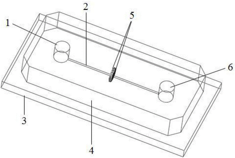
[0050] Combine figure 1 , figure 2 with image 3 , See Image 6 , An inductive reactance oil detection system, including a detection device, a measurement mode switching unit 11, and an excitation-detection unit 12.

[0051] The detection device includes a microfluidic chip and a sensing unit 5. The microfluidic chip includes a microchannel inlet 1, a microchannel 2, a substrate 3, a model material 4, and a microchannel outlet 6.

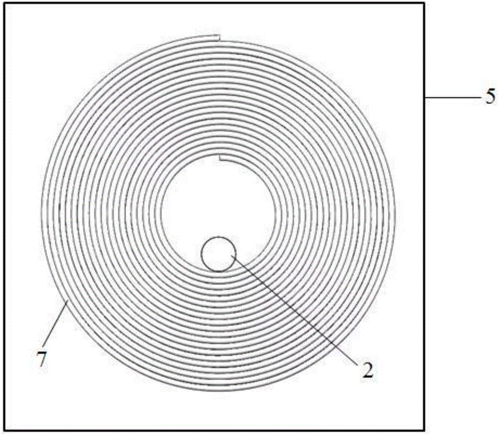
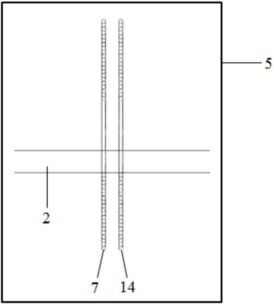
[0052] The sensing unit 5 is composed of two identical first single-layer coils 7 and second single-layer coils 14. The two single-layer coils 7 and 14 are arranged opposite each other, and the microchannel 2 is separated from the two single-layer coils. 7 and 14 pass through the inner holes; the first single-layer coil 7 has a first lead end 15 and a second lead end 16, and the second single-layer coil 14 has a third lead end 17 and a fourth lead end 18.

[0053] The two single-layer coils 7, 14 are wound by enameled wire, the inner diameter of the coil...

Embodiment 2

[0063] See figure 1 with Image 6 The manufacturing method of the inductive reactance oil detection system of the present invention is divided into three steps in total, specifically:

[0064] The first step is to make a detection device. First, fix the micro-channel mold and the two single-layer coils 7, 14 on the substrate 3 at the predetermined position; then pour the model material 4 on the substrate 3 to solidify the model material 4; finally, the micro-channel mold is removed from the cured The model material 4 is extracted, and the two ends of the microchannel 2 are punched with a puncher to form the microchannel inlet 1 and the microchannel outlet 6, and the manufacturing of the detection device is completed. The material of the aforementioned substrate 3 is glass. The four lead ends of the two single-layer coils 7 and 14 are arranged outside the model material 4 and are not poured by the model material 4. The model material 4 is polydimethylsiloxane or polymethyl meth...


PUM

PropertyMeasurementUnit
The inside diameter ofaaaaaaaaaa
Diameteraaaaaaaaaa

Abstract

The invention relates to the technical field of mechanical equipment oil detection and provides an inductive-reactance type oil detection system. The system comprises a detector, a measurement mode switching unit and an excitation-detection unit. The detector comprises a micro-fluidic chip and a sensing unit, wherein the micro-fluidic chip is composed of a micro-channel inlet, a micro-channel, a substrate, a model material and a micro-channel outlet; and the sensing unit is formed by two single-layer coils facing each other. The measurement mode switching unit switches different measurement modes by changing different connection modes of four lead terminals of the two single-layer coils. By supplying the two single-layer coils with high-frequency AC electric excitation, the excitation-detection unit can be used as an inductance-resistance detector as well as a capacitance detector. According to the chip, by the utilization of the same sensing unit, measurement of multiple parameters such as inductance, resistance and capacitance is realized, various particle pollutants in the oil can be distinguished and detected, and fault diagnosis of machinery equipment can be further carried out.

Description

Technical field [0001] The invention relates to the field of equipment oil system fault detection, in particular to an inductive oil detection system for detecting particulate pollutants in oil and a manufacturing method thereof. Background technique [0002] Particulate pollutants in the oil are the main cause of hydraulic system failures. The ability to detect particulate pollutants in the oil is a reliable solution for fault diagnosis of equipment systems. At present, the detection methods for oil particle pollutants mainly include optical detection method, acoustic detection method, inductance detection method, and capacitance detection method. Among them, the optical detection method has high detection accuracy, but cannot distinguish the properties of particulate pollutants, and is limited by the influence of the oil transmittance. Acoustic detection method detects particles in oil by detecting reflected sound waves. This method is more seriously affected by environmental ...

Claims


Application Information

Patent Timeline
IPC IPC(8): G01N27/02G01N27/04G01N27/22
CPCG01N27/02G01N27/04G01N27/221G01N27/223
Inventor 张洪朋曾霖孙玉清陈海泉
Owner DALIAN MARITIME UNIVERSITY
Learn More