
Light fixture for generating power through photovoltaic temperature difference waste heat

A technology of waste heat power generation and temperature difference power generation, which is applied to semiconductor devices, light sources, electric light sources, etc. of light-emitting elements, which can solve problems such as increased contact surface, increased contact surface thermal resistance, and stability effects, and achieves reduced thermal resistance and efficient heat conduction , strong applicability

Inactive Publication Date: 2017-02-08
ZHEJIANG GEMCORE TECH
View PDF12 Cites 4 Cited by
  • Summary
  • Abstract
  • Description
  • Claims
  • Application Information

AI Technical Summary

Problems solved by technology

Although the thermal conductivity of graphite sheets is good, the increase of graphite sheets also leads to an increase of the contact surface. Compared with the structure without graphite sheets, the thermal resistance of the contact surface is also increased to a certain extent.
In the process of production and processing, the increase of graphite flakes also requires higher precision of the process, and has a certain impact on the stability of the product in later use

Method used


Image

  • Light fixture for generating power through photovoltaic temperature difference waste heat
  • Light fixture for generating power through photovoltaic temperature difference waste heat
  • Light fixture for generating power through photovoltaic temperature difference waste heat

Examples


Embodiment Construction

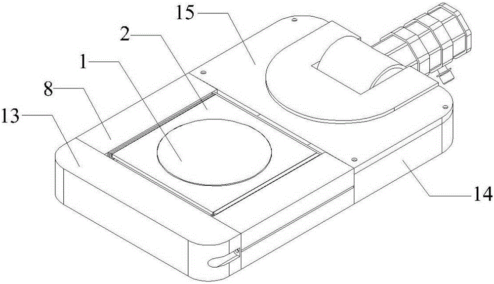
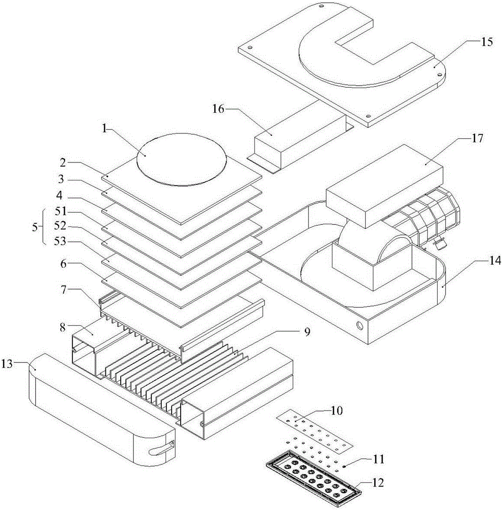
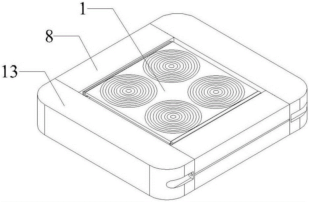
[0024] Such as figure 1 , 2 As shown, it is a preferred embodiment of the present invention, consisting of a condenser lens 1, a glass 2, a protective layer 3, a solar power generation panel 4, a thermoelectric power generation chip 5, an insulating layer 6, a second radiator 7, a bracket 8, a first Radiator 9, substrate 10, LED light source 11, light source lens 12, side cover 13, base 14, cover plate 15, controller 16, energy storage device 17, etc. The lower end of the bracket 8 is fixed with a first radiator 9 , the installation plane of the first radiator 9 is fixed with an LED light source 11 , the upper end of the bracket 8 is fixed with a solar thermoelectric power generation structure, and the front end of the bracket 8 section side is connected with a side cover 13 .

[0025] The structure of solar thermoelectric power generation is mainly composed of condenser lens 1, glass 2, protective layer 3, solar power generation panel 4, thermoelectric power generation chip ...


PUM


Abstract

The invention relates to a light fixture for generating power through a solar cell panel and temperature difference power generation chips and storing the power in an accumulator for driving a light source to emit light. The light fixture comprises a temperature difference power generation module, a solar cell module, a charging adapter, the accumulator, a controller and an LED lamp. The light fixture is characterized in that a first heat dissipator is fixed to the lower end of a support; the LED light source is fixed to the installation plane of the first heat dissipator; a solar temperature difference power generation structure is fixed to the upper end of the support; and a side cover is connected to the cross section side of the support. Due to the fact that the temperature difference power generation chips are directly manufactured between a solar power generation panel and the surface of a second heat dissipator, the light fixture is simple in structure and efficient in heat conduction; heat resistance caused by adoption of heat conduction materials is reduced; and durability of the application process is improved. The structure of the light fixture is applicable to large-batch industrialized production; in addition, applicability is great, and solar energy and the temperature difference can be well utilized for power generation; and the light fixture of the structure provided with the temperature difference power generation chips can save more energy and protect the environment better.

Description

technical field [0001] The invention relates to a lighting fixture, in particular to a lighting fixture which utilizes a solar cell panel and a thermoelectric power generation sheet to generate power, stores it in a storage battery, and drives a light source to emit light. Background technique [0002] At present, existing lamps mainly realize light emission by directly or indirectly converting electric energy into light energy. The electric energy of lamps is generally mainly input from the grid, and solar energy, wind energy, or use of tides, temperature differences, etc. are also used to generate electricity. The light source has evolved from fire, oil lamps, incandescent lamps, energy-saving lamps, fluorescent lamps, LED light sources, etc., to a more efficient and environmentally friendly direction. Through the government's policy guidance and support, as well as the improvement of LED light source technology and the reduction of cost, LED lamps have begun to be gradua...

Claims


Application Information

Patent Timeline
IPC IPC(8): F21S9/03F21S9/04F21V29/76F21V19/00F21V23/00F21Y115/10
CPCF21S9/03F21S9/04F21V19/001F21V23/003F21V23/02F21V29/76
Inventor 诸建平
Owner ZHEJIANG GEMCORE TECH
Learn More