Eureka AIR delivers breakthrough ideas for toughest innovation challenges, trusted by R&D personnel around the world.

Residual heat utilization system of fuel cell and control method

A fuel cell and control method technology, applied in the direction of fuel cell heat exchange, fuel cells, fuel cell additives, etc., can solve the problems of inability to recycle, less heat energy utilization, limited water pumps, etc., to solve the problem of high battery power consumption , the applicable area is limited, and the effect of ensuring the working temperature

Active Publication Date: 2017-02-01
BEIJING ELECTRIC VEHICLE
View PDF8 Cites 14 Cited by
  • Summary
  • Abstract
  • Description
  • Claims
  • Application Information

AI Technical Summary

Problems solved by technology

[0002] The fuel cell stack of an electric vehicle will generate a lot of heat energy when it is working, but the existing electric vehicles make less use of this part of the heat energy, and basically use coolant to take away the excess heat energy to maintain the working temperature of the fuel cell stack
This system cannot re-use the heat dissipated by the fuel cell stack and can only be wasted
In addition, the heat of the fuel cell stack is controlled only by the flow of coolant, which is limited by the capacity of the water pump. If the speed of the water pump cannot be high enough, the water flow will be limited, which may cause the risk of the system temperature exceeding the range.

Method used


Image

  • Residual heat utilization system of fuel cell and control method
  • Residual heat utilization system of fuel cell and control method
  • Residual heat utilization system of fuel cell and control method

Examples


Embodiment Construction

[0054] In order to make the technical problems, technical solutions and advantages to be solved by the present invention clearer, the following will describe in detail with reference to the drawings and specific embodiments. In the following description, specific details, such as specific configurations and components, are provided only to assist in a comprehensive understanding of the embodiments of the present invention. Accordingly, those of ordinary skill in the art should recognize that various changes and modifications of the embodiments described herein can be made without departing from the scope and spirit of the invention. Also, descriptions of well-known functions and constructions are omitted for clarity and conciseness.

[0055] It should be understood that reference throughout this specification to "one embodiment" or "an embodiment" means that a particular feature, structure, or characteristic related to the embodiment is included in at least one embodiment of t...


PUM


Abstract

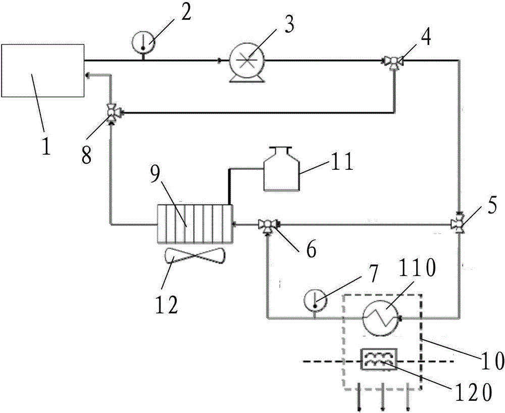
The invention provides a residual heat utilization system of a fuel cell and a control method. The residual heat utilization system of the fuel cell comprises a controller, a first pipeline, a first temperature sensor, a water pump, a first three-way valve, a second three-way valve, a second pipeline, a third three-way valve, a third pipeline, a second temperature sensor, a fourth three-way valve, a fourth pipeline, a heat sink and a warm wind collection device, wherein a first end of the first pipeline is connected with an electric stack of the fuel cell, the first temperature sensor and the water pump are arranged on the first pipeline, the second temperature sensor is arranged on the third pipeline, a first end of the fourth three-way valve is connected with the electric stack of the fuel cell by the fifth pipeline, the heat sink is arranged on the fourth pipeline, and the warm wind collection device comprises an electric heater PTC (Positive Temperature Coefficient) group and a heat exchanger arranged on the third pipeline. With the residual heat utilization system of the fuel cell and the control method, provided by the embodiment of the invention, the working temperature of the electric stack of the fuel cell is ensured, residual heat generated by reaction of the electric stack of the fuel cell is effectively used for warm wind heat supply in a compartment, and the residual heat utilization system is energy-saving and environmental-friendly, is simple in structure and low in limitation of a applicable region.

Description

technical field [0001] The invention relates to the technical field of electric vehicle design, in particular to a fuel cell waste heat utilization system and a control method. Background technique [0002] The fuel cell stack of an electric vehicle generates a large amount of heat energy during operation, but the existing electric vehicles rarely use this part of heat energy, and basically use coolant to take away excess heat energy to maintain the working temperature of the fuel cell stack. This system cannot re-use the heat dissipated by the fuel cell stack, it can only be wasted. In addition, the heat of the fuel cell stack is controlled only by the flow of coolant, which is limited by the capacity of the water pump. If the speed of the water pump is not high enough, the water flow will be limited, which may lead to the risk of the system temperature exceeding the range. Contents of the invention [0003] The technical problem to be solved by the embodiments of the pr...

Claims


Application Information

Patent Timeline
Patent Type & Authority Applications(China)
IPC IPC(8): H01M8/04029H01M8/04007H01M8/04701
CPCH01M8/04029H01M8/04037H01M8/04701Y02E60/50
Inventor 李从心易迪华秦兴权杨世熙刘文月王金龙周金龙龙帆邓立军刘彪张龙聪赵红玉贾立进高璐
Owner BEIJING ELECTRIC VEHICLE
Why Eureka
Eureka Blog
Learn More