
Fodder feeding device

A technology of feeding device and feed, applied in animal feeding device, application, poultry industry and other directions, can solve the problems of high working pressure of motor, high cost, and difficult transformation, and achieve small installation site limitations and low transformation cost. , the effect of simple structure

Inactive Publication Date: 2017-01-18
李亚耕
View PDF6 Cites 3 Cited by
  • Summary
  • Abstract
  • Description
  • Claims
  • Application Information

AI Technical Summary

Problems solved by technology

This feeding method saves time and labor, but the structure is complicated, the cost is high, and the transformation is difficult
[0004] During the use of mechanical feeding, it is found that the feed is easy to adhere to the inner wall of the feeding pipe, and it is easy to deteriorate and become moldy after a long time
It will affect the quality of feed, and then affect the health of livestock and poultry, and affect the quality of livestock and poultry. This feeding method is difficult to achieve feeding work on different planes. Because the feeding spring inside the feeding tube encounters the turning of the feeding tube, or more Turning at the corner, the working pressure of the motor is high, and the material tube is easy to wear
Especially in under-forest farming, only feeding within a fixed range can be achieved, and the discharge port cannot be placed flexibly
The feed in the outdoor feeding tube is easily affected by moisture and deteriorates

Method used


Image

  • Fodder feeding device
  • Fodder feeding device
  • Fodder feeding device

Examples


Embodiment 1

[0035] Embodiment 1: refer to Figure 1-4 , a feed delivery device comprising

[0036] Structure 1:

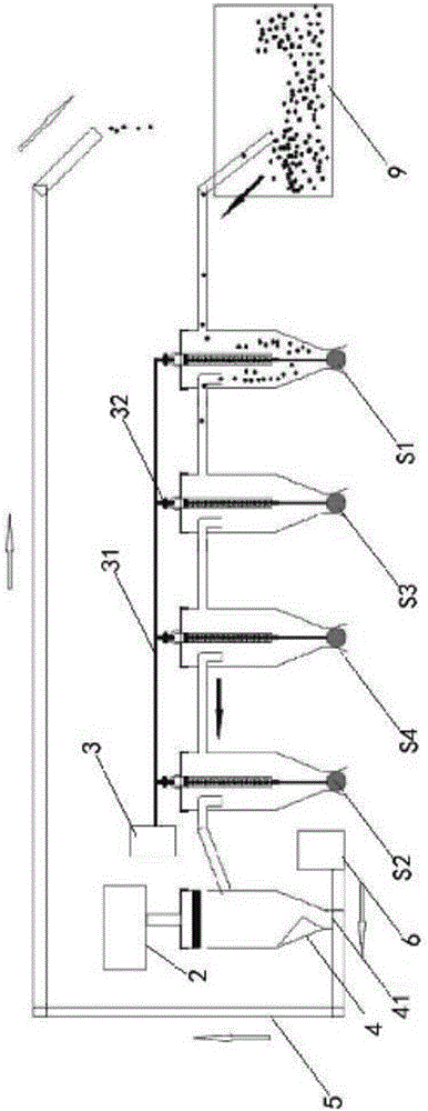
[0037] At least one intermediate group of series-connectable suction hoppers is connected in series between the initial group of serial-connectable suction hoppers S1 and the end-group of serial-connectable suction hoppers S2, and the feed pipe and silo 9 of the initial group of serial-connectable suction hoppers S1 Connection, the discharge pipe of the terminal group can be connected in series with the suction hopper S2 to the suction device 2.

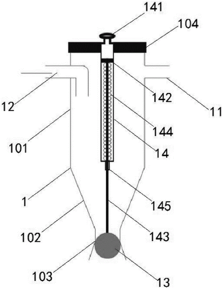
[0038] The initial group of tandem suction hoppers, the middle group of tandem suction hoppers, and the end group of tandem suction hoppers respectively include a sealed hopper main body 1 for accommodating feed, a feed pipe 11 arranged on the hopper main body 1, a row The feed pipe 12 , the discharge device, the feed pipe 11 and the discharge pipe 12 are arranged near the top of the hopper main body 1 .

[0039] The feeding pipe ...

Embodiment 2

[0040] Embodiment 2: On the basis of Embodiment 1, the first intermediate group of serial suction hoppers S3 and the second intermediate group Tandem suction hopper S4.

[0041] The discharge pipe of the initial series-connectable suction hopper S1 is connected to the feed pipe of the first intermediate series-connectable suction hopper S3, and the discharge pipe of the first intermediate series-connectable suction hopper S3 is connected to the second intermediate group. The feed pipe of the hopper S4, the discharge pipe of the tandem suction hopper S4 of the second middle group is connected to the feed pipe of the adjacent group of tandem suction hoppers S2 in the direction of the end.

[0042] The negative pressure of the air extraction device 2 further makes the air flow and feed flow from the initial group of serial suction hoppers S1, the first middle group of serial suction hoppers S3, the second middle group of serial suction hoppers S4, and the end group Tandem suctio...

Embodiment 3

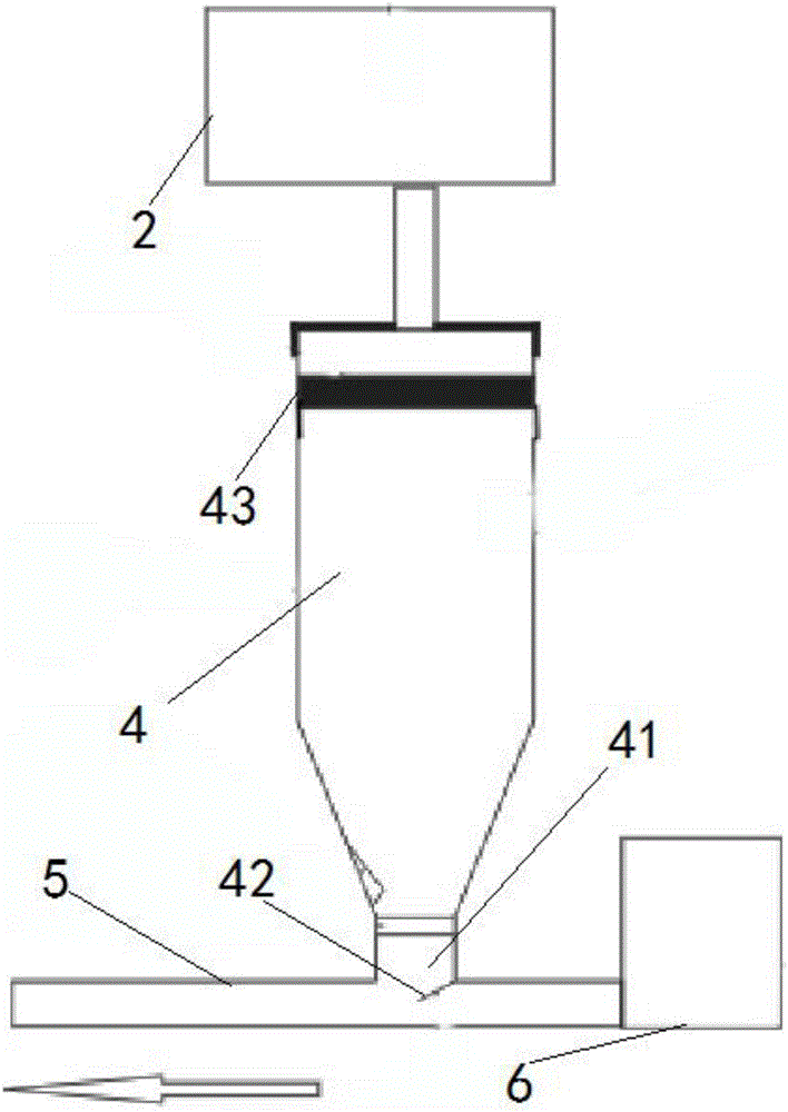
[0058] Embodiment 3: On the basis of Example 1, in order to further recycle the feed, a collection barrel 4 is arranged between the terminal group of the serial suction hopper S2 and the air extraction device 2, and the discharge of the terminal group of the serial suction hopper S2 The tube communicates with the collecting bucket 4, and the air extraction device 2 is connected with the collecting bucket 4 through the negative pressure output pipe.

[0059] A feed filter screen 43 is arranged at the connection between the air extraction device 2 and the collecting barrel 4, and the feed filter screen 43 can effectively prevent feed from entering the air extraction device 2 and cause the failure of the air extraction device 2.

[0060] The bottom of the collection barrel 4 is provided with a gravity induction power-off switch or a pressure-sensing power-off switch connected in series on the power supply circuit of the air extraction device 2. Enter into the collection bucket 4,...


PUM


Abstract

The invention relates to the technical field of livestock breeding design, and particularly relates to a fodder feeding device. The invention adopts the following technical scheme: at least one group of intermediate group tandem suction hopper is connected in series between an initial group tandem suction hopper and a tail group tandem suction hopper; the initial group tandem suction hopper, the intermediate group tandem suction hopper and the tail group tandem suction hopper respectively comprise a sealed hopper main body for receiving a fodder as well as a feeding pipe, a discharge pipe and a discharge device which are arranged on the hopper main body, wherein the feeding pipe and / or the discharge pipe are arranged at the top close to the hopper main body, the feeding pipe of the initial group tandem suction hopper is connected with a bin, and the discharge pipe of the tail group tandem suction hopper is connected with an air extraction device. The fodder feeding device has the advantages that 1, one-source feeding and multi-point discharge are realized; 2, the device is simple in structure, low in cost and suitable for popularization and application, the fodder can be sufficiently recycled, and the device is safe and environment-friendly in the absence of power wires; 3, the device is suitable for being used outdoors, and the fodder attached to the device for a long time is not deteriorated or wetted; and 4, the improvement cost is low, and the limitation to the installation site is low.

Description

technical field [0001] The invention relates to the technical field of animal husbandry design, in particular to a feed feeding device. Background technique [0002] Animal husbandry is a pillar industry of agricultural development and an important source of agricultural income. With the improvement of people's living standards, the demand for meat is also increasing. However, the existing feeding methods of animal husbandry are mainly through manual feeding. or mechanical feeding. [0003] Mechanical feeding mainly includes: hopper, feeding pipe, motor and feeding tray. The bottom of the hopper is connected to the feeding pipe. Inside the feeding pipe is a feeding spring driven by a motor. The blanking port connected with the plate. This kind of feeding method saves time and labor, but the structure is complicated, the cost is high, and the transformation is difficult. [0004] During the use of mechanical feeding, it is found that the feed is easy to adhere to the inner...

Claims


Application Information

Patent Timeline
Patent Type & Authority Applications(China)
IPC IPC(8): A01K5/00A01K39/01
CPCA01K5/00A01K39/01
Inventor 李亚耕
Owner 李亚耕
Learn More