
Self-walking shears-fork type high-altitude operation platform walking hydraulic system

A high-altitude work platform and hydraulic system technology, which is applied in the direction of fluid pressure actuators, lifting devices, servo motors, etc., can solve problems such as slipping and impact, and achieve the effect of increasing service life and improving operation stability

Inactive Publication Date: 2017-01-11
JIANGSU LIUGONG MACHINERY
View PDF5 Cites 2 Cited by
  • Summary
  • Abstract
  • Description
  • Claims
  • Application Information

AI Technical Summary

Problems solved by technology

When walking in a straight line, when the adhesion on both sides is not equal, the system pressure value is related to the maximum adhesion, resulting in the flow tending to flow to the travel motor on the side with low adhesion, but the steering wheel does not deflect at a certain angle , so the walking motor on the side with low adhesion will bear the impact of pressure and even slip.

Method used


Image

  • Self-walking shears-fork type high-altitude operation platform walking hydraulic system
  • Self-walking shears-fork type high-altitude operation platform walking hydraulic system

Examples


no. 1 example

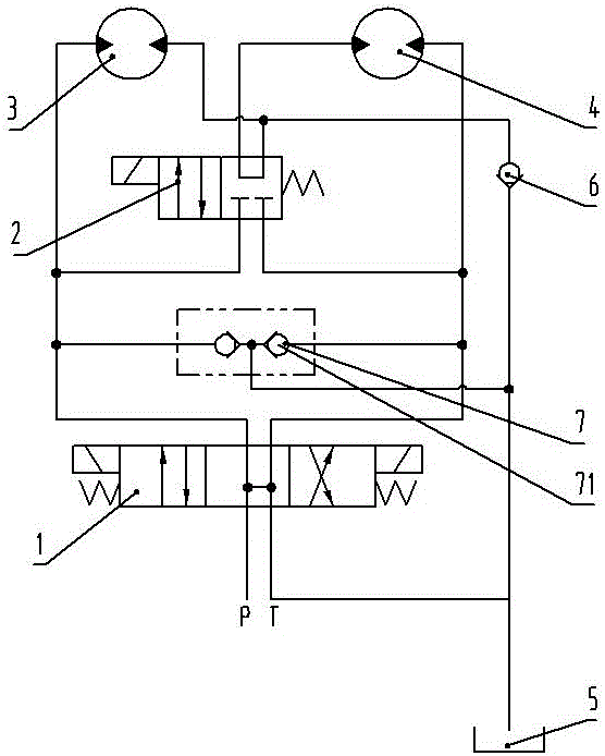
[0014] Such as figure 1 As shown, a self-propelled scissor type aerial work platform walking hydraulic system includes a three-position four-way valve 1, a two-position four-way valve 2, a left travel motor 3, a right travel motor 4 and a hydraulic oil tank 5; The four oil ports in the middle position of the three-position four-way valve 1 are connected to each other, and the oil inlet and oil return circuits of the other two are reversed; the right position of the two-position four-way valve 2 makes the left travel motor 3 and the right travel Motor 4 is connected in series; when two travel motors are connected in series, the high-pressure oil in the system passes through three-position four-way valve 1, left travel motor 3, two-position four-way valve 2, right travel motor 4, and finally passes through three-position four-way valve The four-way valve 1 returns to the hydraulic oil tank 5 . The oil path between the left travel motor 3 and the right travel motor 4 is provided...

Embodiment 2

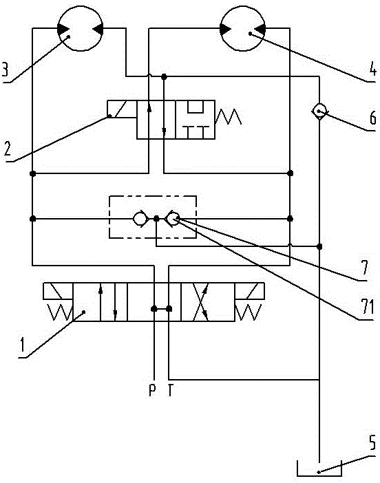
[0017] Such as figure 2 As shown, a self-propelled scissor type aerial work platform walking hydraulic system includes a three-position four-way valve 1, a two-position four-way valve 2, a left travel motor 3, a right travel motor 4 and a hydraulic oil tank 5; The four oil ports in the middle position of the three-position four-way valve 1 are connected to each other, and the oil inlet and oil return circuits of the other two are reversed; the right position of the two-position four-way valve 2 makes the left travel motor 3 and the right travel The motor 4 is connected in series; when two travel motors are connected in parallel and the three-position four-way valve 1 is left, the high-pressure oil in the system passes through the three-position four-way valve 1 and then is divided into two oils which pass through the two-position four-way valve 2 and the left side respectively. Traveling motor 3, the oil passing through the two-position four-way valve 2 passes through the rig...


PUM


Abstract

The invention discloses a self-walking shears-fork type high-altitude operation platform walking hydraulic system which comprises a three-position four-way valve, a two-position four-way valve, a left walking motor, a right walking motor and a hydraulic oil tank. Four oil ports at the middle position of the three-position four-way valve are mutually communicated, an oil inlet circuit and an oil return circuit at the other two positions of the three-position four-way valve are mutually switched, and the left walking motor and the right walking motor are connected in parallel by the left position of the two-position four-way valve. The self-walking shears-fork type high-altitude operation platform walking hydraulic system has the advantages that the problem of air suction abnormal sound generated in turning during walking of a self-walking shears-fork type high-altitude operation platform can be solved, the service life of the walking motors can be effectively prolonged, and operation stability of the self-walking shears-fork type high-altitude operation platform is improved.

Description

technical field [0001] The invention relates to a hydraulic system, in particular to a walking hydraulic system of a self-propelled scissor type high-altitude operation platform, which belongs to the technical field of engineering machinery. Background technique [0002] The self-propelled scissor-type aerial work platform is a kind of machine used to lift people, their tools and materials to the high-altitude work site, and realize self-propelled through the walking hydraulic system. The walking hydraulic system generally consists of a pump, an electromagnetic reversing valve A, an electromagnetic reversing valve B, and two motors. The forward and reverse direction of the motor is controlled by the electromagnetic reversing valve A to realize the forward and backward of the aerial work platform. The series-parallel connection of the motors is controlled by the electromagnetic reversing valve B to realize two motors running in parallel at low speed and running in series at ...

Claims


Application Information

Patent Timeline
Patent Type & Authority Applications(China)
IPC IPC(8): F15B11/16B66F11/04
CPCF15B11/16B66F11/04
Inventor 王现青牛宏杰文强贾志伟
Owner JIANGSU LIUGONG MACHINERY
Learn More