A Linear Array Static Infrared Earth Sensor Optical System

An earth sensor and optical system technology, applied in optics, optical components, instruments, etc., can solve the problems of large image distortion, too small working distance, low optical transmittance, etc., achieve low optical energy loss, and facilitate satellite use , the effect of simple structure

Active Publication Date: 2018-08-31
BEIJING INST OF CONTROL ENG
View PDF3 Cites 0 Cited by
  • Summary
  • Abstract
  • Description
  • Claims
  • Application Information

AI Technical Summary

Problems solved by technology

[0006] (1) The lens is composed of 4 mirrors, resulting in low optical transmittance;
[0007] (2) Although the product is designed with an f-theta optical structure, the imaging target is a plane object rather than a point object, resulting in excessive image distortion and cannot be used by satellites;
[0009] (1) The optical field of view is 21 degrees, resulting in a small optical measurement range and limited use of satellites;
[0010] (2) The rear working distance is too small (about 7mm), resulting in limited installation of optical filters and detectors, and limited installation of thermal control systems of detectors

Method used


Image

  • A Linear Array Static Infrared Earth Sensor Optical System
  • A Linear Array Static Infrared Earth Sensor Optical System

Examples


Embodiment

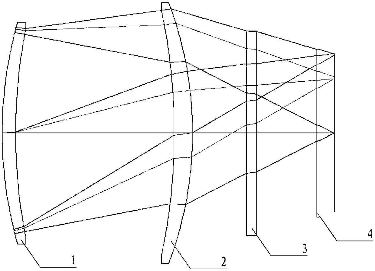
[0041] An embodiment of the present invention has a working spectrum of 14-16 μm, an entrance pupil diameter of 40 mm, and a full field of view of 40°.

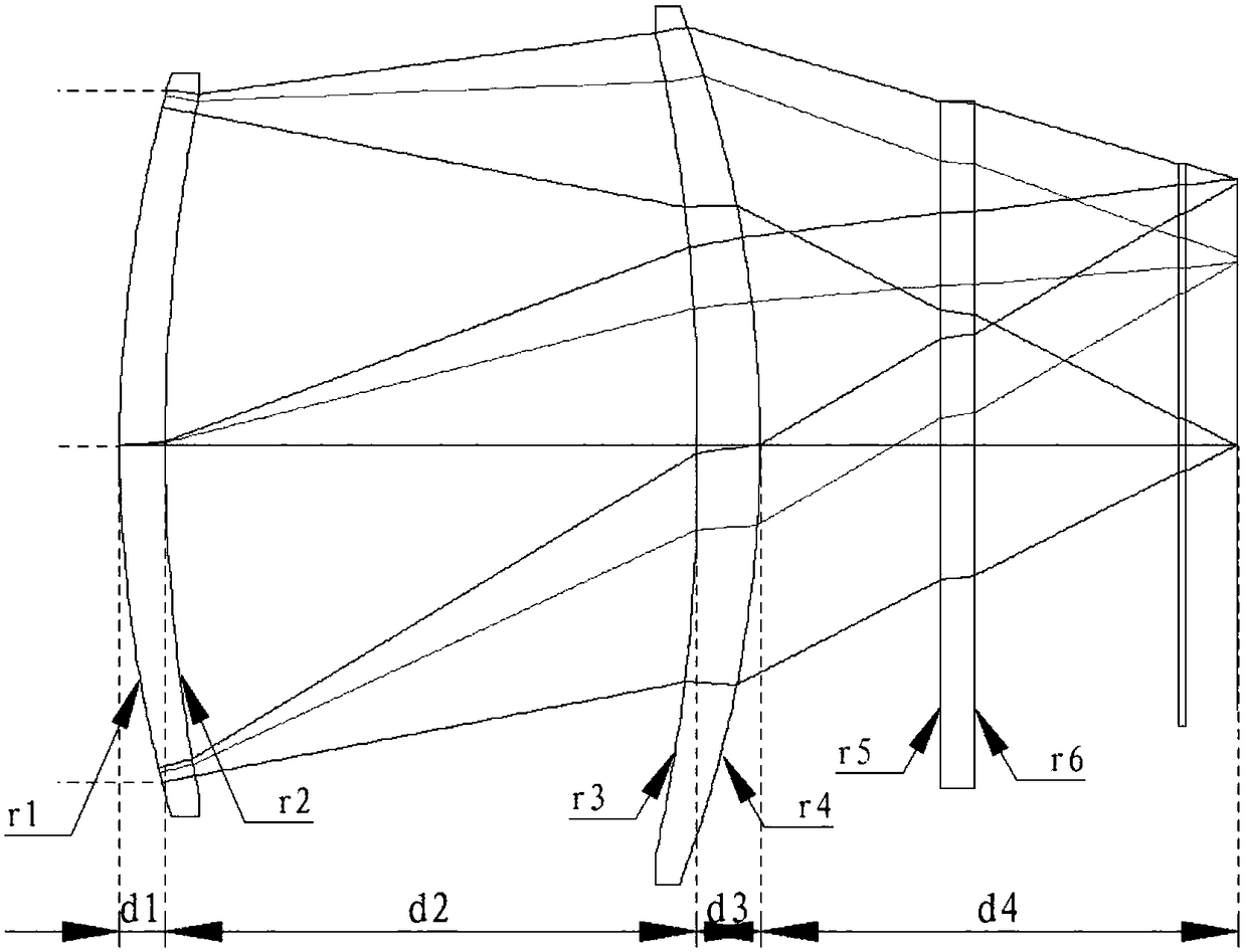
[0042] In this embodiment, the first positive power meniscus mirror 1, the second positive power meniscus mirror 2, and the optical filter 3 are germanium single crystal materials, the first positive power meniscus mirror 1, the second positive power meniscus The surface of the meniscus mirror 2 is coated with a far-infrared anti-reflection film. The optical filter 3 is coated with multiple dielectric films to form a 14-16 μm bandpass optical filter.

[0043] In this example, the surface r1 of the first positive power meniscus mirror 1 is an aspherical surface, and the surface r2 is a concave spherical surface, |R1|=78.8, conic coefficient -2.5, quartic coefficient 3.6E-7, sextic coefficient -3.2E-10, |R2|=109.5 satisfies the relation:

[0044] 70<|R1|<90

[0045] 100<|R2|<120

[0046] Among them, |R1| is the absolute val...


PUM


Abstract

The invention discloses a linear array static infrared earth sensor optical system. A refractive optical structure is realized by using two meniscuses and one filter; a field angle is greater than 30 degrees; for correcting an off-axis aberration, one surface of each of the two meniscuses is set to be an aspheric surface. The system is simple in structure and small in mass; F# is not greater than 1.5, thereby meeting the signal-to-noise ratio requirement of a product; the optical system is realized by using the two meniscuses, the thickness of each of the two meniscuses is not greater than 4mm, the optical energy loss in the meniscuses is low, and the full-field distortion is less than 1%, so that the linear array static infrared earth sensor optical system is especially suitable for being applied to an infrared earth sensor in a spacecraft attitude and orbit control system of a satellite spacecraft and the like.

Description

technical field [0001] The invention belongs to the technical field of infrared earth sensors for attitude and orbit control sub-systems of space vehicles such as satellite spacecraft, and relates to an optical system of a linear array static infrared earth sensor for optical imaging of 14-16 micron far-infrared radiation of the earth. Background technique [0002] The infrared optical system of the linear array static infrared earth sensor (infrared earth sensor, formerly known as infrared horizon) for space vehicles is used to optically image the far-infrared radiation of the earth's atmosphere, and the wavelength is generally 14 to 16 microns. Due to the weak radiant energy, the optical system needs to have a large relative aperture (small F#), few and thin lenses to improve the energy transmittance; it needs a relatively large field of view to increase the measurement range; it needs to suppress distortion and facilitate the satellite use. At present, there is no patent...

Claims


Application Information

Patent Timeline
Patent Type & Authority Patents(China)
IPC IPC(8): G02B13/00G02B27/00
CPCG02B13/003G02B27/0025
Inventor 王伟华周昊李丹凤谭民涛邓楼楼田信灵李硕种会萱苑林
Owner BEIJING INST OF CONTROL ENG
Why Eureka
Try Eureka