An Optical System of Area Array Static Infrared Earth Sensor

An earth sensor and optical system technology, applied in optics, optical components, instruments, etc., can solve the problems of small optical measurement range, large image distortion, too small working distance, etc., to meet the requirements of satellite use and low optical energy loss , the effect of convenient satellite use

Active Publication Date: 2018-08-31
BEIJING INST OF CONTROL ENG
View PDF3 Cites 0 Cited by
  • Summary
  • Abstract
  • Description
  • Claims
  • Application Information

AI Technical Summary

Problems solved by technology

[0007] (1) Although the F# of the optical system is 0.61, the aperture stop of the system is located behind the third lens instead of in front of the first lens. The real energy utilization rate of the system is too low, and the effective F# is only 2.4, resulting in the product The signal-to-noise ratio is too low to meet the requirements;
[0008] (2) The lens is composed of 4 mirrors, resulting in low optical transmittance;
[0009] (3) Although the product is designed with an f-θ optical structure, the imaging target is a surface object rather than a point object, resulting in excessive image distortion and cannot be used by satellites;
[0011] (1) The optical field of view is 21 degrees, resulting in a small optical measurement range and limited use of satellites;
[0012] (2) The rear working distance is too small (about 7mm), resulting in limited installation of optical filters and detectors, and limited installation of the detector's thermal control system;
[0013] (3) The optical system has a low resolution and can only be used for linear array infrared earth sensors, but cannot be used for area array static infrared earth sensors
[0015] (1) The aperture stop of the system is located in front of the second lens, not in front of the first lens. The real energy utilization rate of the system is too low, and the effective F# is 1.6;
[0016] (2) The system distortion is 8.8%, and image correction needs to be performed separately;

Method used


Image

  • An Optical System of Area Array Static Infrared Earth Sensor
  • An Optical System of Area Array Static Infrared Earth Sensor

Examples


Embodiment

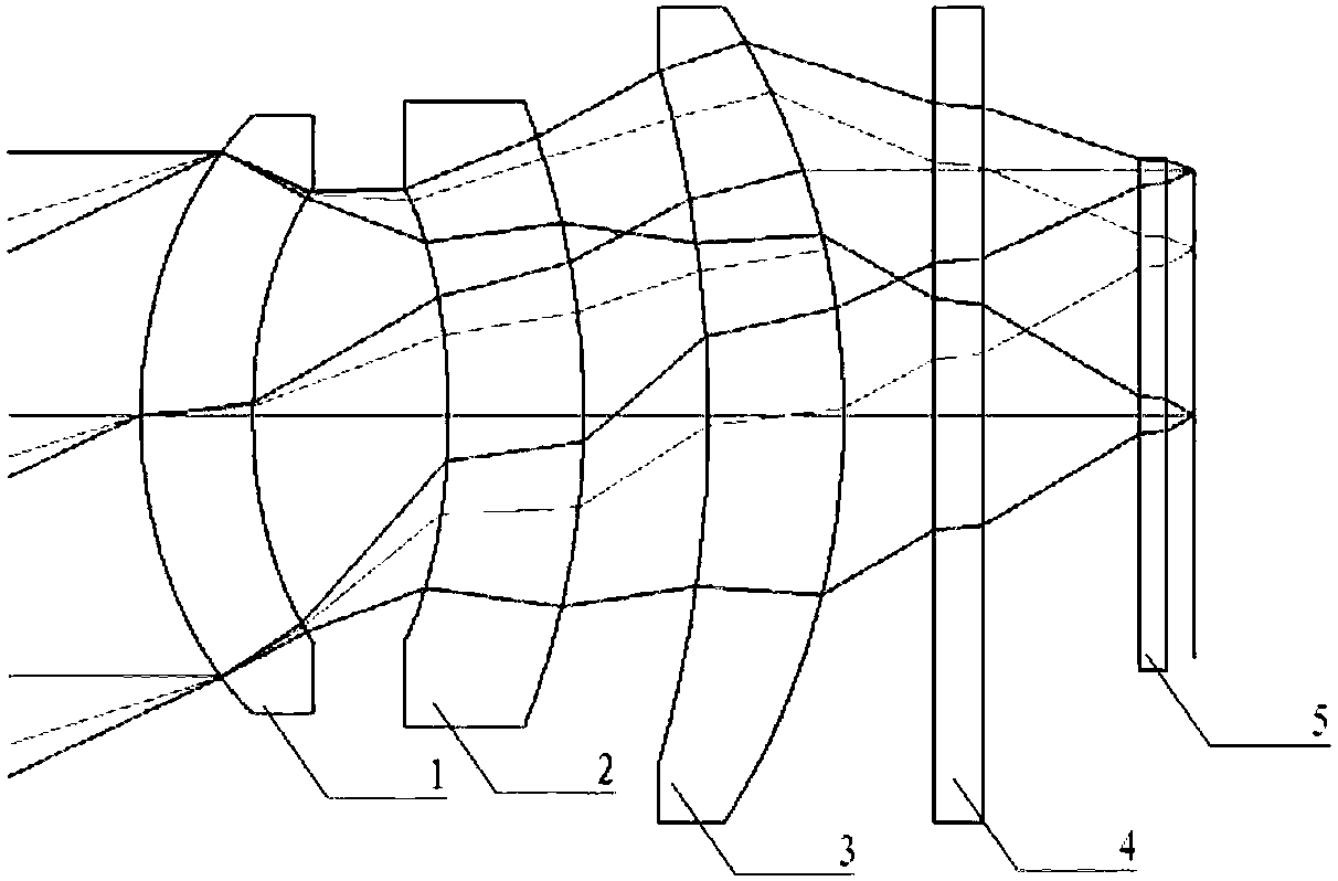
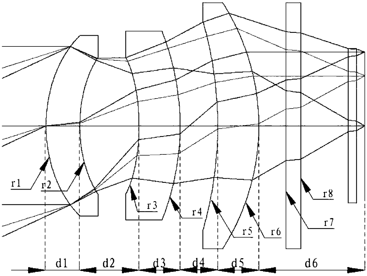
[0053] In this example, the surface r1 of the meniscus mirror 1 with the first positive refractive power is an aspherical surface, |R1|=18, the conic coefficient is -0.7, the quartic coefficient is 4.6E-6, the sixth power coefficient is 2E-8, and the surface r2 It is an aspheric surface, |R2|=18.5, conic coefficient 0.7, fourth order coefficient 2.5E-5, sixth order coefficient 2E-8, satisfying the relation:

[0054] 15<|R1|<22

[0055] 15<|R2|<22

[0056] 0.8<|R1 / R2|<1.2

[0057] Among them, |R1| is the absolute value of the radius of the surface r1 at the vertex, and |R2| is the absolute value of the radius of the surface r2 at the vertex.

[0058] The thickness d1=4 of the meniscus mirror 1 with the first positive refractive power satisfies the relationship:

[0059] 3

[0060] In this example, the surface r3 of the second negative power meniscus mirror 2 is an aspheric surface, |R3|=28, the conic coefficient is 6, the quartic coefficient is 5E-6, the surface r4 is ...


PUM


Abstract

The invention discloses an area-array static infrared earth sensor optical system. A refraction type optical structure is achieved by adopting three crescent moon lenses and an optical filter, and the field angle is 50 degrees and meets the satellite attitude measuring range requirement; four aspheric surfaces are adopted to correct off-axis aberration; the after working distance is larger than 10 mm, and therefore the optical filter, a detector and a thermal control system are conveniently installed. According to the system, the structure is simple, the weight is small, F# is not larger than 1.5 and meets the signal-to-noise ratio requirement of a product, distortion in the full view field is smaller than 0.5%, and the system is especially suitable for being used in infrared earth sensors in attitude orbit control systems of spacecrafts such as satellite spacecrafts.

Description

technical field [0001] The invention belongs to the technical field of infrared earth sensors for attitude and orbit control sub-systems of space vehicles such as satellite spacecraft, and relates to an optical system of an area array static infrared earth sensor for optical imaging of 14-16 micron far-infrared radiation of the earth. Background technique [0002] The infrared optical system of the area array static infrared earth sensor (infrared earth sensor, formerly known as infrared horizon) for space vehicles is used to optically image the far-infrared radiation of the earth's atmosphere, and the wavelength is generally 14 to 16 microns. Due to the weak radiant energy, the optical system needs to have a large relative aperture (small F#), few and thin lenses to improve the energy transmittance; it needs a relatively large field of view to increase the measurement range; it needs to suppress distortion and facilitate the satellite use. At present, there is no patent au...

Claims


Application Information

Patent Timeline
Patent Type & Authority Patents(China)
IPC IPC(8): G02B27/00
CPCG02B27/0025G02B27/0081
Inventor 谭民涛李连升王伟华张崇英田信灵彭慧李丹凤孙艳史永敏安思桦
Owner BEIJING INST OF CONTROL ENG
Why Eureka
Try Eureka