Cooling device for multi-energy-source large-temperature-difference areas

A large temperature difference, multi-energy technology, applied in household refrigeration devices, cooling fluid circulation devices, refrigerators, etc. Improve the energy utilization rate, reduce the amount of water transported and energy consumption, and reduce the power consumption of cold stations

Active Publication Date: 2017-01-04
ARCHITECTURAL DESIGN & RES INST OF SOUTH CHINA UNIV OF TECH
View PDF9 Cites 6 Cited by
  • Summary
  • Abstract
  • Description
  • Claims
  • Application Information

AI Technical Summary

Problems solved by technology

[0004] The main disadvantage of district cooling is the three problems caused by the increase of cold water transportation distance: high energy consumption in transportation; large investment in pipe network; large cooling loss in pipe network
However, this cooling method has the following problems: Due to the limitation of the characteristics of the lithium bromide refrigeration unit itself, the minimum supply temperature of cold water can only reach 7°C
Large temperature difference cooling and low-temperature air supply cannot be realized, and the distance of centralized cooling is limited. In addition, because the temperature difference of cooling is only 5°C (7°C-12°C), the diameter of the cooling pipe network is required Larger, larger initial investment in the pipeline network
The absorption unit itself has low efficiency

Method used


Image

  • Cooling device for multi-energy-source large-temperature-difference areas
  • Cooling device for multi-energy-source large-temperature-difference areas

Examples


Embodiment Construction

[0033] In order to better understand the present invention, the present invention will be further described below in conjunction with the accompanying drawings. All other implementations obtained by those of ordinary skill in the art without creative work fall within the protection scope of the present invention.

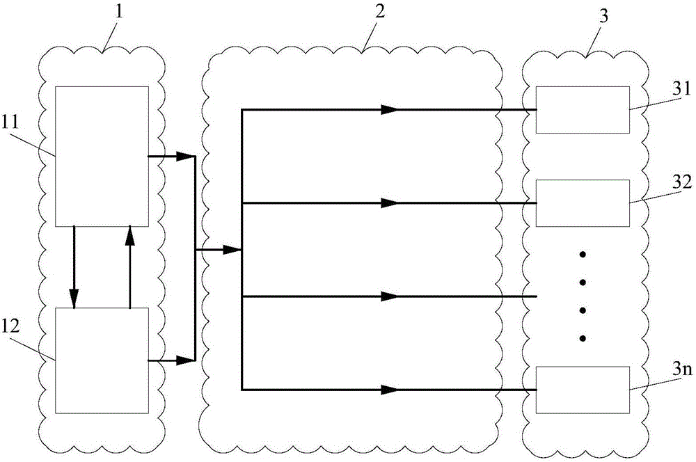
[0034] Such as figure 1 As shown, a multi-energy large temperature difference regional cooling device includes a cooling station 1 , a transmission pipe network 2 and a user terminal 3 . The cooling station 1 mainly includes a refrigeration system 11 and an energy storage system 12; the user end includes a plurality of users, respectively the first user 31, the second user 32, ... the nth user 3n; the cold water produced by the cooling station 1 passes through The delivery pipe network 2 is sent to the user end 3 .

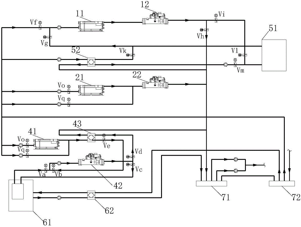
[0035] Such as figure 2 As shown, the cooling station 1 includes a refrigeration system 11, an energy storage system 12, a water separator 71 and a ...


PUM


Abstract

The invention discloses a cooling device for multi-energy-source large-temperature-difference areas. The cooling device comprises a cooling station, a transmission pipeline network and a user side, wherein the cooling station comprises a refrigerating system, an energy storage system, a water distributor and a water collector, a mounted absorption water chilling unit and a mounted centrifugal water chilling unit of the refrigerating system are connected in series, an inlet of the mounted absorption water chilling unit is connected with a reservoir and a chilled water return pipe of the water collector through valves respectively, and an outlet of the mounted centrifugal water chilling unit is connected with the reservoir and a chilled water supply pipe of the water distributor through valves respectively; an inlet of the reservoir is connected with the outlet of the mounted centrifugal water chilling unit and a cold exchange end outlet of an impoundment cooling plate through valves respectively, and an outlet of the reservoir is connected with the inlet of the mounted absorption water chilling unit and a cold exchange end inlet of the impoundment cooling plate through valves respectively. Multiple energy sources can be fully utilized, cooling can be achieved by means of waste heat, gradient utilization of energy can be achieved, and primary energy ratio can be increased.

Description

technical field [0001] The invention relates to the technical field of regional energy combined cooling, heating and power supply, in particular to a multi-energy large temperature difference regional cooling device. Background technique [0002] District cooling is a cooling method that uses centralized large-scale cooling stations to provide chilled water to cooling units within a certain range. Like running water, electricity, and gas, it is a public utility and one of the urban infrastructures. Due to its advantages in energy saving, emission reduction, environmental protection, and operation management, it has won a lot of attention in countries and regions such as Europe and the United States. extensive development. In recent years, many district cooling systems have been put into use in Beijing, Guangzhou, Shanghai, Chongqing, Shaoxing and other cities in my country, meeting people's increasing requirements for quality of life. District cooling (energy) systems are ...

Claims


Application Information

Patent Timeline
IPC IPC(8): F25D3/00F25B41/04F25D3/02F25B15/00F25D17/02F25B41/28
CPCF25B15/00F25D3/00F25D3/02F25B41/20
Inventor 王钊陈卓伦张宇翔
Owner ARCHITECTURAL DESIGN & RES INST OF SOUTH CHINA UNIV OF TECH
Why Eureka
Try Eureka