Heat tube type waste heat boiler system externally arranged beside large flue of sintering machine

A technology of heat pipe type and large flue, which is applied in the direction of furnace, waste heat treatment, furnace components, etc., can solve the problems of non-cumulative utilization, increased floor space, parking accidents, etc., and achieves significant economic and social benefits, and saves equipment investment , the effect of small footprint

Inactive Publication Date: 2017-01-04
江苏中天能源设备有限公司
View PDF0 Cites 0 Cited by
  • Summary
  • Abstract
  • Description
  • Claims
  • Application Information

AI Technical Summary

Problems solved by technology

[0005] (1) The external arrangement places the waste heat boiler outside the main building of the sintering machine, which increases the floor space, equipment support, platforms and pipelines. For sintering plants, most enterprises do not have the conditions for external arrangement;
[0006] (2) The increased bypass flue is difficult to arrange;
[0007] (3) Added 6 large-diameter flue valves and increased equipment investment;
[0008] (4) For the exhaust gas that has the value of waste heat recovery from other air ducts that have not been led out, it cannot be accumulated and utilized, that is, energy cascade utilization cannot be achieved, and the temperature of superheated steam cannot be reliably guaranteed
[0010] The disadvantage of this built-in waste heat recovery device of the sintering machine is that the superheater and the heat pipe evaporator are directly inserted into the large and small flue, and the load changes frequently when the sintering machine is running, which leads to local stress on the superheater and the heat pipe evaporator, resulting in leakage , resulting in a parking accident and affecting the production of the sintering machine

Method used


Image

  • Heat tube type waste heat boiler system externally arranged beside large flue of sintering machine
  • Heat tube type waste heat boiler system externally arranged beside large flue of sintering machine
  • Heat tube type waste heat boiler system externally arranged beside large flue of sintering machine

Examples


Embodiment Construction

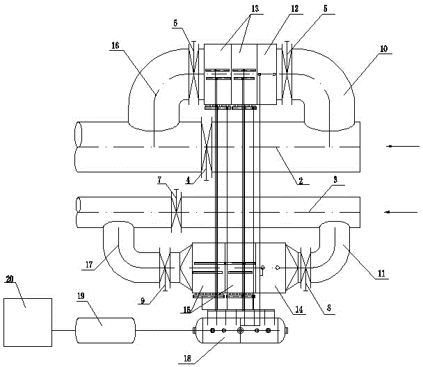
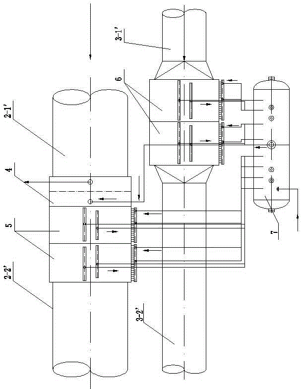
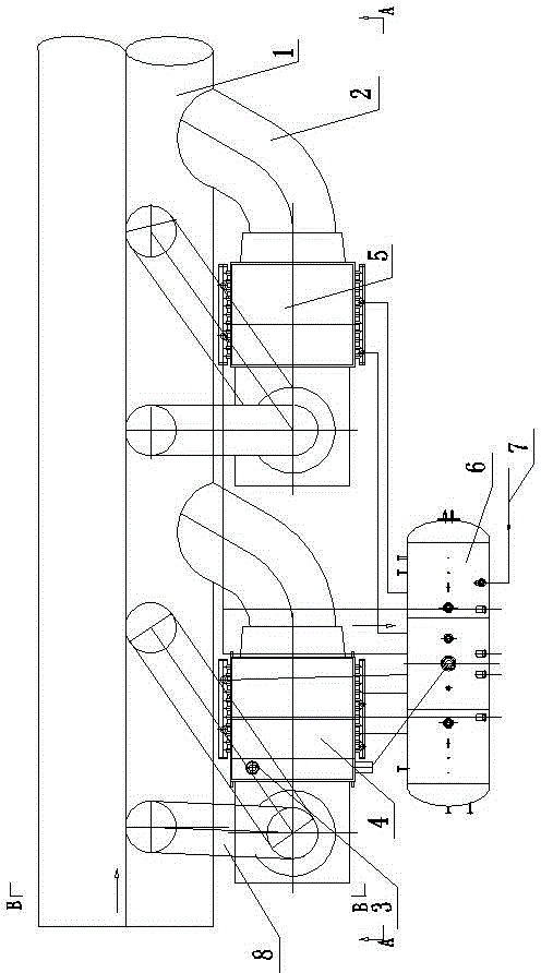
[0022] Such as image 3 , 4 , 5, the present invention includes a large flue 1 of the sintering machine, a bypass flue 2, a steam superheater 3, a primary heat pipe evaporator 4, a secondary heat pipe evaporator 5, a steam drum 6, and a water supply system 7 , a number of air guide pipes 8 are arranged on the large flue 1; the steam superheater 3 and the primary heat pipe evaporator 4 are respectively arranged on one side of the tail of the large flue 1; the secondary heat pipe evaporator 5 is arranged on the primary heat pipe evaporator The tail side of the large flue 1 on the output side of the evaporator 4.

[0023] The flue gas inlet end of the steam superheater 3 communicates with the large flue 1 through the corresponding air guide pipe 8; the flue gas outlet end of the steam superheater 3 is connected with the inlet end of the primary heat pipe evaporator 4, and the primary heat pipe The gas outlet end of the evaporator 4 communicates with the corresponding large flue...


PUM


Abstract

The invention relates to the technical field of steel smelting equipment, in particular to a heat tube type waste heat boiler system externally arranged beside a large flue of a sintering machine. The heat tube type waste heat boiler system externally arranged beside the large flue of the sintering machine comprises the large flue of the sintering machine, bypass flues, steam superheaters, a primary heat tube type evaporator, a secondary heat tube type evaporator, a steam pocket and a water feeding system. A plurality of steam guide tubes are arranged on the large flue. According to the heat tube type waste heat boiler system externally arranged beside the large flue of the sintering machine, because the heat tube type waste heat boiler is directly arranged beside the large flue of the sintering machine, an existing site of the sintering machine is fully utilized to recycle waste heat resources of the sintering machine, reasonable, effective and gradient utilization of energy is achieved, the equipment investment is small, and the occupied area is small; and generated superheated steam is used for power generation, and remarkable economic and social benefits are achieved. Meanwhile, the heat tube type waste heat boiler system externally arranged beside the large flue of the sintering machine cannot influence production of the sintering machine and can be widely applied to the industry of sintering machines of steel enterprises.

Description

technical field [0001] The invention relates to a heat pipe type waste heat boiler used outside a large flue of a sintering machine, which belongs to the technical field of iron and steel smelting equipment. Background technique [0002] In the existing iron and steel production equipment, the waste heat of exhaust gas from the belt cooler or ring cooler of the sintering machine has been generally recycled to generate superheated steam for power generation or other purposes. However, the exhaust heat of the sintering machine itself has not been widely recycled, and only a few iron and steel enterprises have adopted external (built-in) waste heat recovery devices (waste heat boilers, heat pipe steam generators, etc.). As we all know, after the sintering machine is ignited, as the sintering trolley moves from the nose to the tail, the induced draft fan on the flue is used to suck the combustion-supporting air to carry out back-burning. way to the chimney. Under normal circum...

Claims


Application Information

Patent Timeline
IPC IPC(8): F22B1/18F27D17/00
CPCY02P10/25Y02P80/15
Inventor 张玉峰梁怀奇朱俊萍刘文斌
Owner 江苏中天能源设备有限公司
Why Eureka
Try Eureka