Multifunctional support special for milling machine

A multi-functional, milling machine technology, applied in milling machine equipment, details of milling machine equipment, large fixed members, etc., can solve the problem that the bracket cannot be adjusted in height, reduce production efficiency, increase production costs of enterprises, etc., and achieve a wide range of use and reasonable structure. , the effect of increasing stability

Inactive Publication Date: 2017-01-04
张振堂
View PDF6 Cites 0 Cited by
  • Summary
  • Abstract
  • Description
  • Claims
  • Application Information

AI Technical Summary

Problems solved by technology

[0002] The motor shaft is an important part of the rotor part of the motor. The rotor core and rotor winding are fixed on the motor shaft. The output of the motor torque depends on the connection between the motor shaft and the mechanical equipment. The motor shaft must use CNC splines in the traditional processing process. The milling machine processes the side wall of the motor shaft. Before processing, the motor shaft must be clamped on the fixture of the CNC spline milling machine. The height of the traditional support cannot be adjusted. Due to the different heights of the milling machine, different heights are required. In this way, the production cost of the enterprise has been increased and the production efficiency has been reduced. Therefore, it is of great significance to provide a special support for multi-functional milling machines with reasonable structure, easy operation and wide application range.

Method used


Image

  • Multifunctional support special for milling machine
  • Multifunctional support special for milling machine
  • Multifunctional support special for milling machine

Examples


Embodiment 1

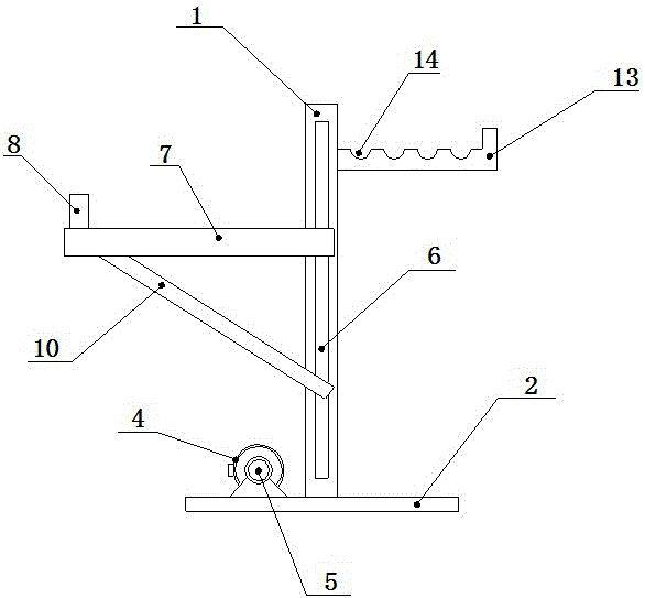
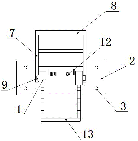
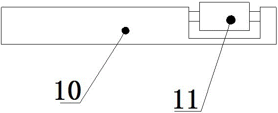
[0016] Such as figure 1 , figure 2 and image 3 As shown, a special bracket for a multifunctional milling machine, which includes a stand 1, the lower end of the stand 1 is provided with a mounting seat 2, and the mounting seat 2 is provided with a mounting hole 3, and on the upper side of the mounting seat 2 An adjustment motor 4 is provided, and the output end of the adjustment motor 4 is connected with a reel 5, and a guide groove 6 is provided on the outer surface of the stand 1, and the stand 1 is connected with an adjustment frame 7, and the adjustment frame 7 The upper side of one end is provided with a limit block 8, the other end of the adjustment frame 7 is provided with a guide wheel 9 matched with the guide groove 6, and the lower side of the adjustment frame 7 is provided with a support beam 10, and the support beam 10 is inclined Set, the support beam 10 is provided with the support wheel 11 that cooperates with the guide groove 6, and the adjustment frame 7 i...

Embodiment 2

[0019] Such as figure 1 , figure 2 and image 3 As shown, a special bracket for a multifunctional milling machine, which includes a stand 1, the lower end of the stand 1 is provided with a mounting seat 2, and the mounting seat 2 is provided with a mounting hole 3, and on the upper side of the mounting seat 2 An adjustment motor 4 is provided, and the output end of the adjustment motor 4 is connected with a reel 5, and a guide groove 6 is provided on the outer surface of the stand 1, and the stand 1 is connected with an adjustment frame 7, and the adjustment frame 7 The upper side of one end is provided with a limit block 8, the other end of the adjustment frame 7 is provided with a guide wheel 9 matched with the guide groove 6, and the lower side of the adjustment frame 7 is provided with a support beam 10, and the support beam 10 is inclined Set, the support beam 10 is provided with the support wheel 11 that cooperates with the guide groove 6, and the adjustment frame 7 i...


PUM


Abstract

The invention relates to a multifunctional support special for a milling machine. The multifunctional support comprises a vertical frame. An installing base is arranged at the lower end of the vertical frame. Installing holes are formed in the installing base. An adjusting motor is arranged on the upper side face of the installing base. The output end of the adjusting motor is connected with a coiling block. A guiding groove is formed in the outer side face of the vertical frame. The vertical frame is connected with an adjusting frame. A limiting block is arranged on the upper side face of one end of the adjusting frame, and a guiding wheel matched with the guiding groove is arranged at the other end of the adjusting frame. A supporting beam is arranged on the lower side face of the adjusting frame and is obliquely arranged. The supporting beam is provided with a supporting wheel matched with the guiding groove. The adjusting frame is connected with a fixed pulley through a rope, wherein the fixed pulley is matched with the coiling block and arranged at the upper portion of the vertical frame. A storage frame is arranged on the right side face of the upper portion of the vertical frame, and a fixing groove is formed in the upper side face of the storage frame. The multifunctional support has the beneficial effects of being reasonable in structure, easy and convenient to operate and wide in application range.

Description

technical field [0001] The invention belongs to the technical field of motor shaft processing equipment, and in particular relates to a special bracket for a multifunctional milling machine. Background technique [0002] The motor shaft is an important part of the rotor part of the motor. The rotor core and rotor winding are fixed on the motor shaft. The output of the motor torque depends on the connection between the motor shaft and the mechanical equipment. The motor shaft must use CNC splines in the traditional processing process. The milling machine processes the side wall of the motor shaft. Before processing, the motor shaft must be clamped on the fixture of the CNC spline milling machine. The height of the traditional support cannot be adjusted. Due to the different heights of the milling machine, different heights are required. Therefore, it is of great significance to provide a special support for multifunctional milling machines with reasonable structure, easy oper...

Claims


Application Information

Patent Timeline
Patent Type & Authority Applications(China)
IPC IPC(8): B23Q1/76B23Q7/00B23C9/00
CPCB23Q1/76B23C9/00B23Q7/00
Inventor 张振堂
Owner 张振堂
Why Eureka
Try Eureka